Finding The Sun And Moon The New Old-Fashioned Way

The ability to build a robot to take care of a tedious task for you is power indeed. For a few centuries, the task of helping determine one’s location fell to the sextant. Now, you can offload that task to this auto-sextant, courtesy of [Raz85].

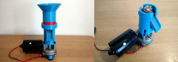
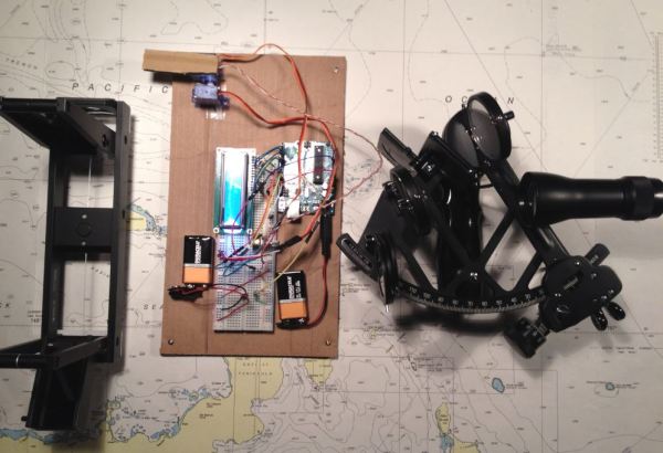
To be clear, this robo-sextant doesn’t give you your exact location, but it does find and display the bearing and altitude of the most luminous object around and display them on the LCD — so, the sun and moon. A pair of cheap servos handle the horizontal and vertical movement, an Arduino Uno acts as the brains and nervous system, and a photoresistor acts as the all-seeing eye. Clever use of some cardboard allow [Raz85] to keep the photoresistor isolated from most all light except what the sextant is currently pointed at. Servos have a limited field of movement, so you might need to adjust [Raz85]’s code accordingly if you’re rebuilding this one yourself.

After taking three minutes to make its rounds of the sky, the Uno records the servos’ positions when fixed on the sun or moon, translating that data into usable coordinates. Don’t forget the best part, it runs on batteries making it convenient for all your wave-faring excursions!

Continue reading “Finding The Sun And Moon The New Old-Fashioned Way”

Language Parsing With ANTLR

There are many projects that call out for a custom language parser. If you need something standard, you can probably lift the code from someplace on the Internet. If you need something custom, you might consider reading [Federico Tomassetti’s] tutorial on using ANTLR to build a complete parser-based system. [Frederico] also expanded on this material for his book, but there’s still plenty to pick up from the eight blog posts.

His language, Sandy, is complex enough to be a good example, but not too complex to understand. In addition to the posts, you can find the code on GitHub.

Continue reading “Language Parsing With ANTLR”

A 3D-Printed Coffee Grinder

It’s safe to say that a Venn diagram of Hackaday readers and coffee drinkers would have significant intersection, many of you will be lovers of the bean. Some of you will be happy enough with a spoonful of instant granules and a bit of boiling water, but among your number there will undoubtedly be owners of significant quantities of coffee-related machinery and paraphernalia.

If your coffee enthusiasm extends to grinding your own direct from the bean, then [Christian Pederkoff]’s project should hit the mark, he’s created a rather neat 3D-printed coffee grinder. Sadly the creation of a steel burr and ring was beyond his 3D-printing capabilities so those parts come from a commercial grinder, but the housing, shaft coupler and hopper are all from his printer. Power is from a conveniently available source, he’s made use of an automotive windscreen wiper motor. The whole is a straightforward and easy-to-assemble unit that we think would sit well alongside many readers’ coffee making equipment.

If coffee projects are your thing, we have a few for your entertainment. Another not quite so neat enclosure for a coffee grinder, for example, or a tea-light-powered filter coffee machine for power cut beverage satisfaction.

Hackaday Prize Entry: Mini DRO For A Lathe

A manual lathe has dial wheels to control the feed of the main carriage and the cross slide to help take cuts on the workpiece. These feed wheels always have some backlash and require frequent resetting of the “zero”. The usual process would be to take measurements on the workpiece with either a vernier caliper or a micrometer at intervals which requires stopping the machine, adding up to increased machine time. The addition of a digital readout not only simplifies the process, but also reduces machining time substantially. Since the DRO magnetic strips are directly attached to the cross slide, the effects of backlash are mitigated.

[Igor] has just such a manual lathe and built his own mini DRO unit from scratch a couple of years back. Most DRO’s have encoder strips and sensors attached to the cross slide with a larger display unit attached separately on a stalk, with wires running between the two. [Igor] kept things simple by building a unit that fit within the space constraints he had. His unit consists of just two sensor modules – each attached directly to the slide. The main unit houses a linear hall sensor, electronics, buttons, a small LCD and batteries. The second axis unit houses just the sensor with a cable connecting it to the main unit for data and power. At the heart of the system is a pair of NSE-5310 linear hall sensor encoder chips. These work in conjunction with multipole magnetic strips. The encoder provides a 12-bit output, and the magnetic strips have poles spaced 2 mm apart. This translates to a theoretical resolution of almost 0.5 microns, but of course, the machine mechanics limit the actual results. The encoder chips talk to an ATtiny2313 over the I2C bus. Three buttons and the power supply round-up the hardware. To run it off a single 1.5 V rechargeable battery, [Igor] used a boost converter to get 3.3 V. The 5 V needed for the LCD is obtained by a voltage doubler connected to a PWM output from the microcontroller and regulated by a Zener diode. The second sensor unit connects via a TRRS 3.5 mm socket.

He added a Bluetooth module as an after thought, but ran out of GPIO pins as well as program space and had to get creative to make it work. The plan was to transmit the data to an Android tablet which would work as a large, remote, wireless display. He never did use that feature though, being satisfied with the small LCD display. There’s several things that went wrong in the build, and if he were to replicate the project again, several changes and improvements would help. So if anyone plans on doing something similar, do check up [Igor]’s project logs first.

It’s Time For Anything Goes In The Hackaday Prize

We’re challenging you to make the best whatever. It’s time for the Anything Goes round of the Hackaday Prize. This is your final chance to enter and we’re looking for just about anything! Twenty entries from Anything Goes will receive a $1,000 cash prize and a chance at the $50,000 grand prize and four other top prizes.

Over the last six months, we asked you to Design Your Concept, and then challenged you to build the Internet of Useful Things, Wheels Wings and Walkers, and Assistive Technologies that ensure a better quality of life for the disabled. All things must come to an end, though, but for the last challenge in the Hackaday Prize, we’re going wild. Is there a theme? No, just go build the best whatever you can. Our one bit of advice: the Hackaday Prize is about Building Something that Matters so do find a way for your “anything” to make the world a little bit better place.

The Anything Goes portion of the prize was introduced in last year’s Hackaday Prize. We didn’t want to exclude anyone building something awesome just because it didn’t fit a theme, so we created a challenge anyone could meet. The results last year were phenomenal, with twenty projects each winning a thousand dollars and progressing onto the final round of the Hackaday Prize. Winners last year included an Open Source Two-Stroke Diesel, a beautiful Diode Clock, and Dtto, a modular robot that went on to win the Grand Prize. Do you see a common theme between these projects? There isn’t one. The Anything Goes portion of the prize is a challenge to build the coolest thing.

This entry round is going on right now and ends October 16th. It’s the last chance for any project to make it to the final round with a potential to take home the Grand Prize of $50,000 USD.

Get those project logs in, and start making a video. Be sure you answer the final call to get in on the 2017 Hackaday Prize.

Switching: From Relays To Bipolar Junction Transistors

How many remote controls do you have in your home? Don’t you wish all these things were better integrated somehow, or that you could add remote control functionality to a random device? It’s a common starting point for a project, and a good learning experience for beginners.

A common solution we’ve seen applied is to connect a relay in parallel to all the buttons we want to press. When the relay is triggered, for example by your choice of microcontroller, it gets treated as a button press. While it does work, relays are not really the ideal solution for the very low current loads that we’re dealing with in these situations.

As it turns out, there are a few simple ways to solve this problem. In this article, we’re going to focus on using common bipolar junction transistors instead of relays to replace physical switches. In short, how to add transistors to existing electronics to control them in new ways.

Continue reading “Switching: From Relays To Bipolar Junction Transistors”

Friday Hack Chat: Elecia White Talks Embedded Systems

The Arduino ecosystem, despite the comments it receives from Real Engineers™, is actually pretty great. There’s no other tool that works with as many varieties of microcontrollers, has as many libraries, and is as easy to use as the Arduino. It’s perfect for getting a project up and running quickly, but when it comes down to getting the last cycles or kilobits out of an embedded system you’ll quickly find the little blue infinity icon just won’t cut it.

Embedded system design goes far beyond the Arduino ecosystem, and for this week’s Hack Chat, we’ll be talking about squeezing the last drops out of tiny pieces of silicon.

Our guest for this week’s Hack Chat will be [Elecia White], embedded software engineer at Logical Elegance, author of O’Reilly’s Making Embedded Systems, and host of the Embedded.fm podcast.  In this chat, we’re going to be talking about moving beyond the Arduino ecosystem.

Topics for this week’s Hack Chat will include embedded systems ecosystems, how to match processors to projects, choosing IDEs, programmers, and other tools, and actually shipping all those whizz-bang microcontroller projects out to eager buyers. We’re opening up the floor to all questions, so if you have something to add, here’s a spreadsheet to guide the discussion.

Here’s How To Take Part:

join-hack-chatOur Hack Chats are live community events on the Hackaday.io Hack Chat group messaging. Hack Chats are mostly, usually at noon, Pacific time on Friday. This week is no exception and everything is going down noon, PDT, Friday, September 8th. Are time zones confusing? Not a problem; here’s a handy countdown timer!

Click that speech bubble to the right, and you’ll be taken directly to the Hack Chat group on Hackaday.io.

You don’t have to wait until Friday; join whenever you want and you can see what the community is talking about.