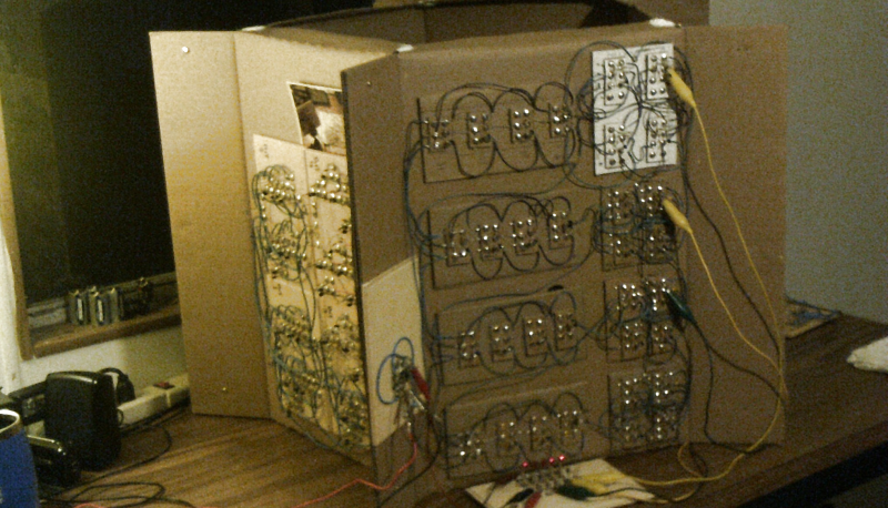
[Dr. Cockroach]’s goal was to build a four-bit computer out of recycled and repurposed junk. The resulting computer, called IO, consists of a single 555, around 230 PNP and NPN transistors, 230 diodes, and 460 resistors. It employs RISC architecture and operates at a speed of around 3 Hz.
He built IO out of cardboard for a good reason: he didn’t have a big budget for the project and he could get the material for free from his workplace. And because it was built so cheaply, he could also build it really big, allowing him to be able to really see each circuit close up and repair it if it wasn’t working right. You can really see the architecture very well when it’s this big—no tangle of wires for [Dr. Cockroach]. He uses over sixty blue LEDs to help monitor the system, and it doesn’t hurt that they look cool too. One of our favorite parts of the project is how he used copper fasteners to both manage the cardboard and serve as wiring points.


Ugh. Blue LEDs. Make them go away.
Lol, The camera picked them up as blue but more a white light otherwise :-)
I suppose all this is inspiration for going back to the BC era and inventing the computer out of rocks and vines.
Spock would have said “Stone knives and bear skins” :-)
Guys? Guys…? This is /way/ hella harder than you think.
A modern computer goes together like Duplo blocks… you put together motherboard, CPU, RAM, graphics card, etc. Big modules, for various tasks. A 70s or 80s homebrew, meanwhile, goes together like a Lego set. It’s a little like a modern computer, but you’re working with DIP chips instead of modules that each have lots of chips on them… pick your CPU, RAM, ROM, peripheral chips, and wire it up. (I can generate schematics for a vintage homebrew in a day or two, depending on datasheet availability and complexity… someone else gets to write the ROM contents, tho.) You might need several chips for a single task (eg a cassette interface) but you can do that because you’re at the chip level… and it’s more flexible (you can’t really make your own modules for modern computers), but the catch is that it’s also a little more complicated, because you have to know where all the dang wires are supposed to go… with modules you just need to know shapes and colors and acronyms — if it fits, it works. Usually.
Now imagine that you have to make the Lego bricks themselves, before you can put the set together. That’s the level that IO sits at. That there is a discrete-component computer. Each little square or rectangle or whatever of cardboard can be thought of as a chip — a set of components put together in a circuit so as to form an integrated whole. Pardon me for pointing it out, but getting something that doesn’t let out the magic smoke on powerup, that alone is relatively difficult. Getting it to /actually freakin’ work as designed/ is another matter entirely, and another order of magnitude more difficult. I speak from experience, here… albeit with relays rather than transistors. I’m not the most inept idiot out there to wield an iron, but I’ve been trying to make relays count pulses off an old telephone dial for so long that I’ve lost track of how many revisions I’ve gone through. No success yet.
IO is not a crazy contraption worthy of derision. IO is a crazy contraption worthy of respect if not real admiration. That’s circuit design and construction on a whole different level. Heck, that’s a /Sixties/ homebrew, to the extent that there is such. Early Sixties.
If you don’t want to believe me, that IO is worthy of praise and admiration and all that good stuff, that’s fine — all I ask is that you try replicating the work yourself before you try and take me apart. I wish you luck in that endeavor, because you’ll need it… and probably, before you’re done, a jacket that ties in the back, as well. That’s a steep uphill climb to a computer-box if I’ve ever seen one.
Thank you :-)
Starhawk: Sorry to hear you never got that dial pulse counter to work.
One approach is to use a synchronous counter: three DPDT relays and a couple diodes per a synchronous D latch (edge-triggered), and out of those you can make synchronous counters. Simon Winder made a telephone dial counter that way for a stand-alone relay-based square root calculator – a very cool finished project, google it. His old webpage is defunct but still available on the wayback machine.
Another approach is to use a ping-pong counter: two registers cross-connected via an incrementer, and the clock alternates the load signals to them. I ended up using the ping-pong scheme in a few places in my own design since it made the circuitry simpler.
The bah-humbug directed to this project is a reminder Xmas is coming.
I love blinky lights, what can I say :-)
I predict every few months we´ll see it again.
https://hackaday.com/2017/01/18/the-cardboard-computer/
Thank you John for the write up :-)
Some would say you’d have to be insane to attempt that in the first place, but there is one way that can help to preserve what sanity you have remaining. Implement the entire circuit functionality on an Arduino in an emulated form then you can build and test each module with progressively less of your functional modules being emulated on the MUC until eventually everything is working on your hardware.
Very impressive tenacity, and cardboard as a base material is quite an idea. Great work, and I hope Mark will bring this to a fully usable state one day.
All those copper tacs remind me of the projects in the usborn electronics books from a “few” years back.
I bet this guy has them on his shelf ( I know I’ve got a few ;) )
Choosing to Delve into something like this kind of project, I wonder if it comes about as a way to learn about how an MCU operates or to demonstrate how one operates.
It’s great work by the way.
Sorry to say that I don’t have any of those books but perhaps someday…It’s a case of both. Learn about and demonstrate how these circuits work.
Wow, this is one of the most pleasing simple CPU designs I’ve seen. Excellent work Mark! What a sight! If it ever gets boring to tinker with, you’ve still got the best decoration in town.
The scale of it is very pleasing, too. This is tremendous work and something you could do over a summer to “become one” with some industry fundamentals.
Cardboard computer filmed on a paper camera? :) Just kidding, great work.
Well, close… I did make a cardboard pinhole camera for the recent solar eclipse :-)
Comment formatting experiment