Wall fans for circulating hot ceiling air

Winter Is Coming: Keeping Heat Where It’s Needed

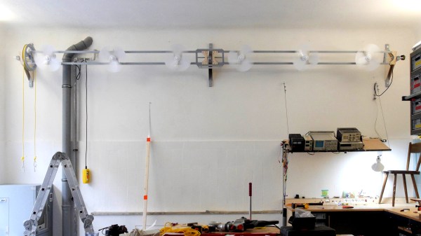
If your workshop has ceilings as high as [Niklas Roy]’s 3.6 meters (11.8 feet), then you’re familiar with his problem. Hot air rises, and there it usually stays until the heat is transferred outdoors. But in the winter time we need that heat indoors and down low. One solution is to install ceiling fans that blow that hot air back down. However, [Niklas] often builds tall things that would collide with those fans. And so he had to hack together some wall hugging fans which will be both high up and out of the way.

Corroded industrial controller

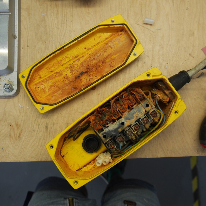
For the fans he’s using six of those ubiquitous standing fans, the ones that normally sit on a post a few feet off the ground and swivel back and forth. Discarding the posts, he mounted the fan bodies to a horizontal wooden frame with a wheel attached to one end, one that he’d made for another project. A rope around the wheel, and hanging down, makes it easy to tilt the fans. For controlling the fans, a friend had given him an old industrial controller, and opening it up, all he saw was corrosion. Cleaning it all out he installed an old Russian 3-position switch from his collection.

In the future he’d like to add a closed-loop control system that would not only turn the fans on and off but also adjusting their speed. For now, however, he reports that it works really well. Check out his page for build photos and more details.

Meanwhile, winter really is coming to these northern latitudes and so here are more hacks to prepare you. For automated shovelling snow, how about an RC controlled 3D printed snow blower. And while you’re snug and warm inside remotely controlling your snow blower, you can still be getting exercise using a DIY bicycle roller. But if you do venture outside, perhaps you’d want to zip around on a dogless dog sleigh.

Scribble Your Way To Quick Printed Circuit Boards

There are a variety of techniques employed by electronic constructors seeking the convenience of a printed circuit board without the inconvenience of making a printed circuit board. Dead bug style construction in which the components float on a spiders-web of soldered leads above a ground plane is one, Manhattan style construction in which pads made from small cut squares of bare copper-clad PCB are glued on top of a groundplane is another.

[Freestate QRP] has another take on this type of electronics, with what he calls “Scribble style” construction. He cuts away copper from bare board to create pads and rudimentary tracks, and for him the magic ingredient comes from his choice of an engineer’s scribe to do the job. This is where the “scribble” comes from, creating a pad is as simple as drawing it with the scribe.

Of course, this technique is not entirely new, constructors have been doing this type of work for years with Dremel tools, hand engraving tools, and similar. If you’ve ever tried to do it with a knife or scalpel you will know that it’s hardly an easy task with those hand tools so the prospect of another one doing a better job is rather interesting. He’s ready and able to demonstrate it in action, showing us a couple of RF circuits using the technique.

Have you tried this technique, or one like it? How did you get on, tell us in the comments. Meanwhile, you might like to read our own [Dan Maloney]’s look at dead bug and Manhattan construction.

Hackaday Links Column Banner

Hackaday Links: September 10, 2017

Hackaday is 13! We’re going through a bit of a rebellious phase. There’s hair where there wasn’t hair before. Thirteen years ago (Sept. 5, 2004), [Phil Torrone] published the first Hackaday Post. [Phil] posted a great writeup of the history of Hackaday over on the Adafruit blog — we were saved from the AOL borg because of the word ‘hack’ — and interviewed the former and current editors of your favorite DIY website. Here’s to 13 more years and to [Phil] finding a copy of the first version of the Jolly Wrencher designed in Macromedia Flash.

Hackaday is having an unconference in the UK! Tickets for next weekend’s event went fast, but don’t worry — we’re hosting a Bring A Hack the day before.

Hurricanes are an awesome force of nature. As we learned from Harvey a week ago, livestreamed footage from the eyewall of a hurricane is fascinating. [Jeff Piotrowski] seems to be the streamer of choice. If you’re looking for something to gawk at, here you go.

Another burn is over, and I still have no idea how they moved the fuselage of a 747 from Palmdale to the playa.

You know we’re doing this whole Hackaday Prize thing where we’re giving a ton of money to people for creating cool hardware, right? We’re almost done with that. The last round of The Hackaday Prize is going on right now. The theme is anything goes, or rather there is no theme. The goal of this round is to build cool stuff. This round ends on October 16th, and yes, we’ll have the results for the Assistive Technologies round out shortly.

[Prusa] makes a lot of printers, and that means he needs to make a lot of parts to make a lot of printers. Obviously, a PTFE-cutting robot is the solution to this problem

October 5th is the Open Source Hardware Summit in Denver. Hackaday and Tindie are going, and it’s going to be a blast.  The location has moved in the last week — now it’s about half a mile away from the old venue. The speaker schedule is up, board nominations are open, and somewhere, someone is organizing a Lulzbot/Sparkfun booze cruise the day after the summit. I should be getting a van to add capacity to this trip, so if you’re interested leave a note in the comments.

Hackaday Prize Entry: IO, The Cardboard Computer

[Dr. Cockroach]’s goal was to build a four-bit computer out of recycled and repurposed junk. The resulting computer, called IO, consists of a single 555, around 230 PNP and NPN transistors, 230 diodes, and 460 resistors. It employs RISC architecture and operates at a speed of around 3 Hz.

He built IO out of cardboard for a good reason: he didn’t have a big budget for the project and he could get the material for free from his workplace. And because it was built so cheaply, he could also build it really big, allowing him to be able to really see each circuit close up and repair it if it wasn’t working right. You can really see the architecture very well when it’s this big—no tangle of wires for [Dr. Cockroach]. He uses over sixty blue LEDs to help monitor the system, and it doesn’t hurt that they look cool too. One of our favorite parts of the project is how he used copper fasteners to both manage the cardboard and serve as wiring points.

Continue reading “Hackaday Prize Entry: IO, The Cardboard Computer”

A Great Guide To Software PLLs

There are some things that you think you know quite well because you learned them in your youth and you understand their principles of operation. Then along comes a link in your morning feed that reminds you of the limits of your knowledge, and you realize that there is a whole new level of understanding to be reached.

Take Phase Locked Loops (PLLs) for example. You learn how they work, you use them for frequency synthesis, and you know they can do other things like recover noisy clock lines and do FM demodulation. But then you read [Paul Lutus’] Understanding Phase-Locked Loops page, and a whole new vista opens.

He’s discussing PLLs in the context of software, as part of a weather fax decoder project, and this allows a perspective that was unavailable to those of us who learned about them through the medium of hardware such as the venerable 4046 CMOS chip. We can easily look at different PLLs with varying parameters, for example their use with a narrowband loop filter to retrieve signals buried in the noise, all through some straightforward code tweaks rather than extensive circuitry. It’s a page that’s a few years old now, but resources like this one do not age.

If PLLs are entirely new to you then you need to reat last year’s excellent PLL primer by Hackaday’s own [Al Williams].

[via Hacker News]

[PLL diagram: Chetvorno CC0]

LiPo Added To LEGO Power Functions Power Brick

LEGO’s Power Functions elements mostly consist of DC motors and the hardware to be driven by those motors like gears and wheels. They also include battery packs, usually a bunch of AA cells in a plastic box. One of the challenges of the system — for hackers, anyway — is interfacing with the product line’s plugs, which resemble 2×2 plates with power and ground connectors built in, designed to be impossible to connect in reverse. It’s difficult to make the physical shape of the plug, with the connectors right where they should be. This hurdle means you also pretty much have to use LEGO’s power boxes or take your chances with frying your components from an unregulated LiPo.

The LiPo Power Brick project serves as a DC-DC power supply, serving up constant 9 V output, with
over current protection limiting current to 3 A peak or 2 A continuous and over-discharge protection shutting down the power supply when it zeroes out. It can be used in conjunction with Sbrick smart Power Functions controllers. The SBrick can also source 3A per channel, which is more than any LEGO PF-compatible power supply can deliver.

The LiPo Power Brick is the same size as a standard 2×4 brick, allowing you to easily add it to your next project.

Bodging On More Flash Memory

[Curmudegeoclast] found himself running out of flash memory on a Trinket M0 board, so he decided to epoxy and fly-wire a whopping 2 MB of extra flash on top of the original CPU.

We’ll just get our “kids these days” rant out of the way up front: the stock SAMD21 ARM chip has 256 kB (!) of flash to begin with, and is on a breakout board with only five GPIO pins, for a 51 kB / pin ratio! And now he’s adding 2 MB more? That’s madness. The stated reason for [Curmudegeoclast]’s exercise is MicroPython, which takes up a big chunk of flash just for the base language. We suspect that there’s also a fair amount of “wouldn’t it be neat?” in the mix as well. Whatever.

The hack is a classic. It starts off with sketchy wires soldered to pins and breadboarded up with a SOIC expander board. Following that proof of concept, some degree of structural integrity is brought to the proceedings by gluing the flash chip, dead-bug, on top of the microcontroller. We love the (0805?) SPI pullup resistor that was also point-to-point soldered into place. We would not be able to resist the temptation to entomb the whole thing in hot glue for “long-term” stability, but there are better options out there, too.

This hack takes a minimalist board, and super-sizes it, and for that, kudos. What would you stuff into 2 MB of free flash on a tiny little microcontroller? Any of you out there using MicroPython or CircuitPython care to comment on the flash memory demands? 256 kB should be enough for anyone.