
Do you remember your first oscilloscope? Maybe we have entered the era in which younger readers think of a sleek model with an LCD screen, but for the slightly older among us the image that will come to mind is likely to be a CRT-based behemoth. Mine was a 2MHz bandwidth Cossor from the 1950s, wildly outdated by the 1980s, but it came to me at no cost. It proudly proclaims itself as a “Portable Oscillograph”, but requires its owner to be a weightlifter to move it. I still have it, as a relic and curio.
For most of us a new ‘scope is still a significant investment. Even affordable current models such as the extremely popular Rigol instruments are likely to cost several hundred dollars, but offer measurement functions undreamed of by those 1950s engineers who would have looked on the Cossor as an object of desire.
Oscilloscope buyers on a budget may not have the cash for a Rigol, a Hantek, or any of the other affordable ‘scopes. Someone starting on the road of electronic engineering can scout around for a cheap or free second-hand CRT model, but thanks to the ever advancing march of technology they also have another option. Modern microprocessors and microcontrollers have analogue-to-digital converters and processor cores that are fast enough to provide the functions of a simple oscilloscope, and to that end a variety of very cheap ‘scopes and ‘scope kits have come on the market. These invariably have a rather small LCD screen and a relatively low bandwidth, but since they can be had for almost pocket-money prices their shortcomings can be overlooked in the name of value. It’s been a matter of curiosity for some time then: are these instruments any good? For around £16 ($21) and the minor effort of an online order from China, we decided to find out.
 If you look at most stockists of electronic kits these days, you are likely to find an oscilloscope kit in their range. These are volume produced in China, and the same design trends appear across different models. You can buy surface mount or through-hole, and most of them feature a bare board with maybe a piece of laser-cut Perspex standing in for a case. There are one or two models appearing that come with a case though, and it was one of these that we ordered. The JYE Tech DSO150 is a single-channel ‘scope with a 2.4″ 320×240 pixel colour LCD screen and a 200kHz bandwidth. Its specification is typical of the crop of similar kits, though its smart case sets it apart and made it an easy choice.
In the Box
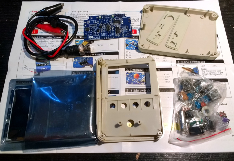
We ordered one, and when it arrived, it was packed in a small cardboard carton that had suffered some crushing in transit, but had protected the internal contents well enough that no harm had been done. A layer of foam protected the LCD, and the case parts appeared rigid enough to protect the rest of the components. There was a bag of discretes, the case parts, two PCBs, a test lead with crocodile clips, and two pages of instructions.
 When looking at a kit, it’s best to start with the instructions, because no matter the quality of the kit itself it is the quality of the instructions that make or break a kit. If you can’t build it then it doesn’t matter how good it might be, it’s effectively junk.
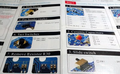
The DSO150 instructions are two sheets of high quality double-sided colour print, with the emphasis on pictures rather than words, The front page introduces the kit and gives a quick soldering guide, then the next two pages step through each stage of construction. The final page has basic instructions for use, specification, and a troubleshooting guide. Our kit had all surface-mount parts already fitted, if we’d known the kit could also be had with SMD parts to fit we’d have bought that version instead.
The instruction steps are long on images and short on text, but there are sometimes few cues as to where the component in question lies on the board. Sometimes some careful examination of board and picture is necessary to ensure correct placement. The first step though doesn’t involve any soldering, wire the main board up to a 9V supply, and watch the LCD boot into the oscilloscope software. There is support via a forum on the JYE Tech website, we presume you’d go there if it failed to boot out of the box. A 9V PSU isn’t included, you’ll need to find one with a 2.1mm centre positive plug. Fortunately a suitable candidate was in the box of wall warts here, formerly being used by a router.
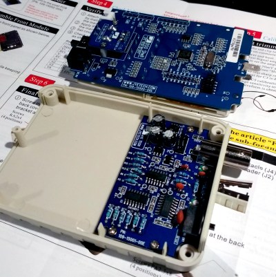
The main board assembly is straightforward enough, being the assembly of larger through-hole parts such as switches and connectors. The analogue board has a brace of small through-hole resistors and ceramic capacitors to fit, of these the resistors were of the tiny variety which made distinguishing between some of their colour stripes a little difficult. Bring your multimeter to check. There is a BNC connector that requires significant heat on there too, so make sure you have a suitably beefy iron to hand. Finally there is a small board for the rotary encoder, then the front of the case can be assembled to the main board, the analogue board attached, and the ‘scope set up. Verify on-board voltages, attach the test clip to the calibration output and adjust the compensation capacitors for a square wave, and the rest of the case can be added to complete the unit.
Functionality
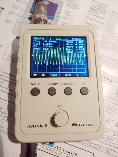
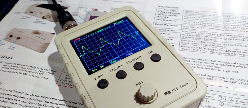
In use, the DSO150 makes a simple and straightforward enough oscilloscope. The usual volts/division and timebase selection is easy enough, and the various trigger modes can quickly be selected. If you’ve used an oscilloscope before then you will have no problems getting started with it. But of course, the DSO150 isn’t just a simple oscilloscope, it’s a digital storage ‘scope. And with 1024 sampling points it can do the usual storage ‘scope thing of allowing the user to examine a stored waveform in great detail, scrolling back and forth through the stored points. Here the instruction sheet falls short, not mentioning that a double tap on the V/div or Sec/div buttons allows you to scroll.
Connecting the signal generator to our DSO150 allowed the exploration of its bandwidth. The claimed 200kHz is pretty spot-on, winding the signal generator far beyond that point showed a tail-off in displayed amplitude. Also the minimum 10µS per division limits the usefulness of a waveform display at these frequencies.
The DSO150 is supplied with a short test lead terminated in a pair of crocodile clips. This is somewhat less useful than the oscilloscope probes we’re used to, though happily it can also be used with a standard 1x/10x probe. Looking at the square wave on the test terminal through a standard probe reveals a sharp corner on the waveform, so there seems not to be any problems between the compensation on-board and that in the probe. It’s likely that either the DSO150 here will be used with a standard probe, or that the crocodile clip will swiftly be replaced with a probe of some kind.
Closing Thoughts
So then, the JYE Tech DSO150 oscilloscope kit. A nice little ‘scope within the limitations of the STM32F103C8 microcontroller that drives it. If you can put up with a 200kHz bandwidth and a 50V peak input voltage then it’s a useful pocket instrument. Its calibration will depend on the STM’s crystal and voltage reference, but as with the rest of its specification, when you consider its pocket-money price those become minor considerations. Add in that its software is open-source, and you have a very nice platform indeed. If we wanted to nitpick we’d ask for a battery compartment and a proper probe, but since both of those would put up the price we wouldn’t make too much noise about it. If you need a pocket ‘scope to supplement your bench scope when working on lower frequencies, or if you have a youngster in the family looking for their first ‘scope, buy one! Our review unit will definitely see some use rather than gathering dust.


Long time ago I wish I had one of these. It’s a super cool tool.
The best thing they could do is to get one of those STMs with 2 ADC and make it a dual channel version. No need for more BW which would make it a lot more expensive like those DSO nano.
The bandwidth seems about right for automotive service. Not very many automotive sensors exceed that. But I have to agree with the dual channel part. I once replaced a camshaft sensor on an old Ford and the calibration required a dual channel scope to align it to the crankshaft sensor at idle.
Not just automotive, but 2 channels is the minimum useful for debugging stuff because you can see 2 things relative to each other. As a lot of things tend to be periodical, you can still debug a multi channel thing with only 2. But there is little you can do with 1.
An external trigger input, while not as useful as a second channel, can be extremely useful for troubleshooting relative timing stuff. The 200KHz bandwidth is the part that makes this a nerf tool in my book.
The F103C8 mentioned in the article is one of those parts. Either they’ve used both ADCs for a single channel, or they’ve decided to only do a single channel.
I missed that, so there is room for improvement. The schematic does kind of show almost all pins are used…
The older model (DSO138) can be modified to become a full dual channel, here’s the link: https://github.com/ardyesp/DLO-138
Please note that so far the DSO150 is still not supported by this mod: https://github.com/ardyesp/DLO-138/issues/1
It now apparently is: https://github.com/michar71/Open-DSO-150
@Bernhard,
Unless I read it wrong, this open version is still 1 analog signal but adds up to 3 digital input.
Still a great improvement to use on mixed-signal projects.
I have a project wher I will demodulate an FSK carrier. That will be great to see along the analog input and the digital output of the demodulator.
the shell for the battery pack is on sale on ebay http://www.ebay.it/itm/202192077271?var=&ssPageName=STRK:MESELX:IT&_trksid=p3984.m1555.l2649
Clicking on the “Purchase” button on the link shows “Starting at $39”
http://accudiy.com/index.php?main_page=product_info&cPath=3_10&products_id=204&zenid=370e4b577b8943ea52ed24535f0b6498
My first O-scope was a Bell and Howell that came in a kit form for a correspondence course (assembled by the original owner) I paid $80, it had a dim display (a High Voltage upgrade was available for purchase) one channel, and IIRC, 5MHz bandwidth.
I have that same Bell & Howell scope sitting right here. I built it with my father when he was learning electronics on the GI bill. That was a great course that left us with really cool instruments for the time.
Mine came from Banggood.
or get it on aliexpress for $22 with shipping.
Around 24 USD on eBay with free shipping, and around 21 USD on AliExpress.
Even cheaper on AliExpress, the 11-11 only € 15,96
Be aware that most DSO* on Aliexpress/Ebay are clones, which doesn’t mean they won’t work but they probably don’t use same quality parts and often lack in testing.
I got mine from Banggood ($20)
https://www.banggood.com/Orignal-JYE-Tech-DS0150-15001K-DSO-SHELL-DIY-Digital-Oscilloscope-Kit-With-Housing-p-1093865.html?p=P81820131902201302WD
“10µS per division” – I very much doubt it, unless you are using it as a transistor curve tracer
A curve tracer requires and external input…………. This scope has none……….
You’ve missed the point!
er, Jenny, any technical results of your testing?
– “The claimed 200kHz is pretty spot-on” – so what was its 3dB point?
– How does it handle a (moderately) fast-edge square-wave?
– Noise level?
– Actual resolution? (it claims 12-bit but I suspect that’s what the ADC outputs rather than the ENOB value)
– Accuracy?
– Jitter?
Interesting point. Yes, I didn’t subject it to a full-on exhaustive evaluation of its performance as a high quality piece of test equipment. I could have dug out my avalanche pulse generator and given it a go for instance, but decided not to. Why? It’s not a high-performance piece of test equipment but a toy scope kit, and the review is of it as a kit rather than a critical review of it as a scope. As a toy scope it’s good enough as a “My first scope”, and for the purposes of this review it’s more pertinent to see that a teenager could build it.
I would like to know how it compares to something like the DSO Nano Oscilloscope v3 which seems to occupy a similar niche, with the difference being one is a finished product and the other is a kit build. Any opinions?
Fair enough.
I was just thinking that, while there are some who may be able to look beyond what JYE claim in their spec to know how much (or not) to trust it, it could be helpful to further others people’s understanding and at least give a bit more weight to how worthwhile it is a ~£15 (okay, it’s not going to be as fast/deep/sensitive as a £100 scope but it is better than 15% accurate?)
Hmm, might be interesting to get a range of cheap scopes (such as the ones Al has reviewed recently) and show people just what you get for the extra money – not just in terms of pure features (channels, >MS/s, longer captures, etc) but also the bits that they tend not to be a bit more, er, artistically described such as the resolution or bandwidth, plus what they don’t talk about (such as pulse response/overshoot)
The chip can do 12 bits at 6 or 7MHz if 3 ADC channels are configured right. Did you notice if more than one pin is being used? That would give about 12 samples per cycle at 500MHz and look OK.
That totally sounds worth more investigation, if it means perhaps a couple of wire links could give you that. Substituting a couple of the passives, perhaps adding a wire-end component or two in parallel with some of the SMDs, or removing an SMD, that’s all stuff you could do without having to be great at soldering.
I don’t agree with you here and I totally think you should test it properly.
Why? Either it’s a toy and thus neither worth testing nor recommendation. If it’s a fancy kit, then I’d be interested in the kit building process and not the oscilloscope functionality. If it’s a complete toy, such a writeup is moot, as there are other cool toys that don’t seem to pose as something they aren’t as well. However, if it’s not a toy, having a rough grasp of what this can do would be immensely helpful. Especially interesting would be the comparison to other oscilloscope kits (there seem to be three common ones: The very old and completely useless AVR-based one (from jyetech as well), one with a red PCB (the DSO138) and now this DSO150. Especially between the latter two, which one wins a shootout? Why? They are attractively priced for standalone units, even if they aren’t especially great. Also interesting would be the comparison to Hantek’s slightly (as in about twice the price) more expensive 6022BE USB scope; less portable, but seems to be reasonably capable. As far as measurements go, I’d be mostly interested in the sample rate and the analogue bandwidth. If you can measure it, clock stability over temperature would be nice to know as well, especially for the portable scopes, but that’s not so important. I don’t really care about effective resolution, they aren’t precision measurement devices by a long shot, certainly not as a kit at this price point. But the interesting question would be: Can you actually do reasonable measurements with them? Real 200 kHz analogue bandwidth with a sensible sample rate (i.e. 5 to 10 times the bandwidth) might afford you to just debug some fast-mode (about 400 kHz) I2C communication, which is totally in the ballpark of hobbyist-level usage for an oscilloscope; of course everyone and their dog has a cheap cypress-ez-usb-based logic analyzer, and they’re incredibly practical, but a scope affords you to look at actual waveforms; a logic analyzer won’t tell you that your slew rate is too slow, but when you see this trace on an oscilloscope, you’ll definitely figure it out.
So, measurement suggestions:
1) -3dB bandwidth
2) Sample rate
3) what does a fast, steep pulse look like? Are there any artifacts from bad anti-aliasing filters?
4) Can you debug fast-mode (400 kHz) I2C?
5) What’s the trigger like? Very basic or somewhat usable?
6) Finally, can you use the oscilloscope to figure out the length of a long cable by using TDR? Modern microcontroller pins have insane slew rates (AVR seems to be pretty good in this respect, for whichever reason), so they can totally generate a pulse into a cable for TDR. The reflected pulse won’t be very nice, so this might be some kind of informal test of the ADC quality: Can you clearly see the reflected pulse without knowing in advance where it should be? What’s the minimum voltage you can use for this pulse before it becomes too hard to spot directly? This is a somewhat roundabout test of noise and resolution, wrapped in a somewhat realistic scenario.
“Either it’s a toy and thus neither worth testing nor recommendation.”
Why in the world would a toy not be worthy of testing or recommendation? Of course it’s a toy. It’s 200 kHz, for crying out loud
“Finally, can you use the oscilloscope to figure out the length of a long cable by using TDR?”
It’s got a minimum time per division of 10 us! A 10 microsecond long cable is ~two miles long. I could be wrong, but I’d have to guess that Jenny doesn’t have a two mile long cable to try to TDR. Heck, even at 10X bandwidth the timestep would be 500 ns, so you’d get an amazing TDR resolution of about +/- a few hundred feet.
Let me explain:
– A toy is something with no use except playing around with. If the purpose of the kit is to be used as a toy, I’d have liked to see a review of the quality as a soldering kit, explanation of the underlying schematics, software and operation theory. The purpose of a toy oscilloscope is to learn how an oscilloscope works. This is easier if it’s low-bandwidth, as no fancy HF design whatsoever needs to take place, and no fancy assembly-DMA-magic-programming is required.
– If it’s not a toy but has some limited use, I would have liked to get a grasp of what that limited use might be. That requires some minimum amount of testing. My measurement suggestions were for cheap oscilloscopes in the “is this even reasonably usable?” category and not just this model. I should have made this clearer. TDR is obviously nonsensical with a 200 kHz bandwidth oscilloscope.
However, a division is not a well-defined unit. How many samples are contained in the 10µs division?
To me, this oscilloscope ranks in the toy category due to the lack of a second channel. With a second channel, it might be an ultra-cheap scopemeter to just carry around, IF it can manage I2C.
????♂️ I’m pretty stoked about my weekend project and being able to check basic analog signaling or PWM. Some see it as a toy, I see it as a $50 hands on crash course in the basics for the same cost as a weeks worth of Starbucks.
The STM32F4 line offer 3 x 2.4 MS/s ADCs. Combining those would reasonably get to 1 MHz for a single channel.
Could you hook it up to an Arduino and some other bits (e.g. LCD display) and test to see how useful it would be for diagnostics coupled with one of the cheap Saleae Logic knockoffs. I think that would be a really valuable article for folks starting out with limited budgets. Also of use to people with larger budgets who want to get some experience before dropping a lot of money on kit.
I was using a 5 MHz, recurrent sweep Heathkit in the 80’s while pursuing a PhD. Most everything else other than VOM & DMM were scratch built. You don’t make much money as a grad student and books took all of mine.
the ‘F303 has 4 ADCs at 5Msps, which is even cooler. But to get good analog capable of the required BW and quality it gets quite expensive.
and $8 LPC4370 has 80MHz 12 bit ADC, used in SDRplay where it reliably delivers 10MHz analog BW
6 or 7 Ms/S will give you 1Mz of sine wave only with 6 samples per cycle, which is going to look pretty bad and not tell you much, including the amplitude One probably needs to filter the input to cut off at 1/8 the sample rate then digital filter after conversion to cut sharper – maybe 1/16. This gives a “visual bandwidth” that fits the stated bandwidth. If the bandwidth is 1MHz, then you want to see a 1MHz sine wave when the input is a 1MHz square wave. 16 samples per cycle will give an OK view of the signal and ignore comments about Nyquist. You won’t tell anything about >2 samples per cycle data without an infinite amount of data collection. (You can’t do exactly 2 because the output will be an arbitrary constant in the range +-amplitude).
Why did your router need a box of wall warts?
Sorry ;-)
Hmmm… Not really open source as the scope-functions are only distributed as a binary blob library.
But, (seamless plug…) if you want to hack around with it here’s a fully open source implementation adding more functionality.
https://github.com/michar71/Open-DSO-150
Haven’t done anything on it for some time but winter is coming….
Hey, that looks interesting. Are there any big bugs floating around that code at the moment?
How are the controls when using multiple waveforms?
… nice! Thanks – gonna try it.
I have the DSO138 with the acrylic case. I saved a whole $2 by soldering the surface-mount parts myself. The DSO150 is definitely a nice upgrade with the better case and the rotary encoder. The portability of both these units is very much hampered by the need for an external PSU. With a beefier 5v regulator, it could be powered from auto or boat 12v.
My DSO138’s input chain seems a little noisy.
I bought a DSO Nano v2 a couple of years back. It’s nicely packaged and has a Li battery pack, so it’s truly portable. I also have a good ole Hitachi 20MHz dual-trace scope which I bought new some 25 years ago.
These little digital scopes are pretty useful for basic work, within the bandwidth. And it’s so cool to be able to single-trigger and review the captured waveform. The Nano will take an SD card for storing waveforms for later viewing – great for analyzing streams.The Nano in particular is easy to bring into the field, or to whip out for one or two tests. My ‘138 will end up on the bench or desk, possibly with some arrangement for quickly patching into oscillators etc.
The kit DSOs are definitely a great first scope for the novice, and almost a no-brainer at the price.
Does anyone knows the specifications for the voltage range if the prob is across voltages under test? Will it be fried?
Page break!
These things look like fun toys but I would caution about recommending them as an alternative to a “real” scope, even to low-buget beginners. Why? The bandwidth! Even your ancient, first scope from the 1950s had 5 times the bandwidth. 1950s!!!
You also wrote “Someone starting on the road of electronic engineering can scout around for a cheap or free second-hand CRT model,”. Now that is much better advice for someone trying to actually obtain a tool for real use. That one partial sentence gets kind of lost in there though.
So.. kids and other beginners… I know that CRTs are incredibly un-cool these days. They are big, heavy, power hungry and just scream “last millennia”. But… they are inexpensive and some are still useful. Just check out the “completed items” listings on Ebay. Someone who otherwise might have bought this 200KHz single-trace toy could save just a little longer and probably end up with a dual trace beast that can do 100MHz or more. Sure… you do lose the storage ability but just take a picture with your phone or something.
Don’t get me wrong… these do look like FUN toys. I am glad that you reviewed them Jenny List. I may get one just for fun one day. I just don’t think “hey new person, you can start with one of these” is good advice.
Now… if maybe they would combine their scope with the features of a multimeter and/or maybe one of those cheap semiconductor testers… that would be something I couldn’t resist buying.
Can’t disagree. But think of it as a gateway instrument, I’d expect a kid with one of these to graduate to a s/h CRT fairly quickly.
Uncool? Take it from an 18 year old, that blue glowing line is one of the coolest things I’ve seen
My kit arrived 2 days ago.
I actually got it for much less ($3.50) but I think the store made a typo, The temptation was to buy all 5 that were available at the time but I thought it was a bit mean taking advantage of them like that. I will offer to pay the difference and see what they say :)
This kit is a pretty good intro to an oscilloscope and will be a useful addition to the workshop. And I think a good item to add to the electronics course I hold. The students get a good assembly tutorial and end up with a useful tool. Totally recommended!
There are a lot of videos about it on Youtube to help too.
Is it possible to power this with lithium batteries without introducing noise? I see it needs 9V input, which internally goes to a LDO and Op amp rails. I don’t want to put the batteries in series either so I can place a small LiPo or Li-on inside with a charger. If I add a DC-DC converter I suspect that there will be noise, or is there a boost converter which would not produce that much noise for this case?
The DC-DC noise can be a killer. I’m working on a system right now that uses an instrument designed to run off a nominal 12V, and is usually powered by a battery in a box. It digitizes sensor inputs in the millivolt range. To get it to work cleanly off a solar-charged system, we had to do a 15V DC-DC, filter the output, and power it through a 12V linear regulator.
If you’re doing this as a one-off, I think it’d be easier to to find/make a compact 3-cell pack, and use a cheap external cell-balancing charger. Check out RC suppliers like HobbyKing.
The trouble you went through is probably why this runs on 9V. Particularly with the crappy quality of using an unknown 9V power supply, it’ll need a lot of voltage overhead to regulate to something stable. I can’t think why it needs 9V, the CPU’s presumably 3.3V, the LCD something similar. Examining the circuit diagram might tell you what’s the minimum it’d run from.
It might run from a noisy 9V from a DC-DC convertor. Maybe stick a big capacitor and a couple of little ones in parallel with the output.
The unit really needs only 7.5 volts to power the LM7805 regulator for the analog board. The “9v’ also feeds a ICL7660/MAX7660 voltage converter to feed an LM7905 regulator, also for the analog board.
I suppose that 9 volt “wall warts” are easier to find than 7.5 volt ones.
FYI, I think the 9v also directly feeds the LCD backlight. More interestingly, I can confirm that “9V” lithium rechargeable batteries (which are actually 2S pouch cells inside of the pp3 case with protection circuitry, so really 8.4V max) does work just fine with this device, and those batteries are just a bit over $5 each on Amazon and often come with a charger.
noise is the last thing you should be worried about if your intent is not learning to solder your first electronic kit, but to actually use this toy to look at signals
Look for a DSO Nano – they are well-packaged for portable use and have Li battery-packs built-in that charge from USB. By the time you turn one of these single-board cheapies into a battery-powered Franken-Scope, you will have blown past the $99 (in time and materials) that the Nano costs..
Whenever I see such a Toy-o-scope I dust off my GBDSO and just smirk…
When men were men, and Toy-o-scopes were… cartridges for real Toys!
So it is about useful for audio but forget even I2C and SPI.
Depends. If you are trying to debug your stuff and can turn down the bitrate, both SPI and I2C can work slow enough to be visible. If you are just observing the device, then not much you can do… better get one of those cheap logic analyzers that can still do a few Msps
Thery’re good for catching and looking at pulses and transients, inspecting the format of most serial streams or simply confirming that the stream is running, looking for dirty DC power supplies (use a blocking capacitor so you just get the noise), inspecting switch or relay bounce, relay coil flyback (defective suppressor diode), dirty motor brushes, …
My first oscilloscope was a Made in USSR ОМЛ-2М. It was awesome little machine.
https://youtu.be/6e1sxB6wols
I don’t read Russian, but from Greek I would guess that says something like “Okcaylograph”. Is that close? :-)
Not even close to Greek, it’s Cyrillic alphabet, and oscilograph=осциллограф
a bit strange to just slap the entire article on the feed. I know.. I know.. “featured”. But why?
People desperate for absolutely bottom dollar scope thing should check out Jinhan JDS2023 handheld unit, $125 free shipping($115 alliexpress). 2 channels 200Msamples, shockingly real 20MHz of actual usable BW at that ridiculous price point, +shitty couple MHz signal gen as a bonus.
https://www.eevblog.com/forum/testgear/chinese-oscilloscope-jds2012a-teardown/msg1247811/#msg1247811
$21 for 200KHz is just throwing money away, unless you treat it as soldering lesson.
Interesting link.
And yes, I’ve reviewed it as much as a soldering kit for a younger electronic enthusiast. It’s a useful toy, but nevertheless a toy.
I acquired mine from BANGGOOD for US$14. That was on Sept. 8th, 2017. The price went up by popular demand.
The kit wasn’t too difficult to build. One of the compensation caps in mine was off but I haven’t bothered to tune it. As Jenny mentioned, the operating instructions missed some detail but I think that’s because the “double-click” feature was added in recent firmware that came out after the instructions were printed.
As mentioned, there have been some reviews on the internet, even some hacks to add a flat LiPoly battery and improve the noise floor. Look at the JYE Tech forum for some instructions. The battery power issue is that there are LM7805 and LM7905 regulators on the analog board. These regulators need 7 volts input to regulate to 5 volts, so the minimum input voltage to the DSO150 is about 7.2 volts. In order to use a single-cell LiPoly battery, you’ve got to boost the 3.0 volts to 7.2 volts. The best efficiency I’ve found is about 93% on a MT3608 module from eBay, which is adjustable. I’m still awaiting some parts to engage in my own battery hack.
I did a small review on the MT3608 module here: https://mt3608stepupmodule.wordpress.com
Thanks for the review Jenny. :)
Peace and blessings.
I wish all these cheap Chinese scopes didn’t have cases that look like (and sometimes literally are) reused MP3 players.
At least this one has a case. So many are just bare PCB.
Before I got the Rigol ds1054z I was planning to make a 3 channel 6MHz dso using the pic32mz. It has a high speed usb 2 interface which enables it to transfer the data directly to pc with 8 bit per channel at 18MB/s. Stand alone it can still do 500KB of sampling. The mcu is about 15 dollars so it’s more expensive but pretty capable, with on board comparator which can be used as trigger at a certain level. It’s probably fast enough to do some basic arithmatics like subtract and addition. The problem with even faster sampling rates is you can’t get the data in the memory of the mcu quick enough, using qspi. You’d be looking at fpga controlled parallel dacs and dram at that point.
I put the guts from a usb-rechargeable 9v lipo battery in mine. Plenty of room for the flat cells and the board. Works great!
Overall I like the scope a lot. The UI is world’s better than any of the other pocket kit scopes.
WARNING: on Aliexpress and EBay there are fake DSO150 kit clones. Other than an overall low quality assembly (I had to debug two bad SMD solders to make it boot), any firmware update will detect them as counterfait and brick them. No way to go back, as the modified firmware they come with is not available to download.
Here is the list of the known counterfait vendors: https://www.jyetech.com/forum/viewtopic.php?f=19&t=1229
This is how to spot the original from the fake: https://www.jyetech.com/forum/viewtopic.php?f=19&t=1212
DSO150 Scope
JYE Tech DSO-SHELL DSO150 15001K DIY Digital Oscilloscope Kit With Housing
Nicely made.
1. Before assembling and testing: Read the instructions 2 or even 3 times to avoid making serious mistakes.
keep ALL components in sealed envelope, they are very small, easy to lose.
2. measure with ohm meter each resistor tape down to a piece of paper with the value.
A soldering mistake will be difficult to correct , the resistors with leads are very small.
be careful to use solder that leaves minimum rosin a magnifying glass is REQUIRED
clean with alcohol (denatured alcohol is poisonous don’t drink it)
3. make sure the test of the LCD is done according to the instructions. look for a scrambled signal which is NOT
clear in the poor instruction photo.
4. keep the assembly area CLEAN, use a piece of white paper to work on.
Analog amplifier has a clever design !
observerms (electronics engineer )
I just received a partially assembled kit, no soldering required. I wouldn’t call it a toy but I don’t think it can be used for precise measurements. On the test mine indicates 1.127kHz signal. My frequency counter says it is spot on at 1kHz. Visually it also looks like 1kHz.
I’ll use mine to visualize servo and stepper signals where precision isn’t critical. I do have a 100mHz scope but due to lack of room it’s usually in storage so only gets pulled out if Absolutely necessary. I think I’ll use this little one quite a bit.
Well, if you have to fix bad solid state analog audio stuff it is quite effective in chasing down lost signal. I paid over 100 times the $22 USD price of the DSO150 for my Fluke Scopemeters, and had to insure them too. . . These now get the digital diagnosing tasks while the little 150 is in my pocket – just in case.
Rotary encoder choked and disintegrated first day.
Ordered new encoder and seller sending a whole new ds0150.