[Tommy] at Oskitone has been making hardware synth kits for years, and his designs are always worth checking out. His newest offering Space Dice is an educational kit that is a combination vintage sci-fi space laser sound generator, and six-sided die roller. What’s more, as a kit it represents an effort to be genuinely educational, rather than just using it as a meaningless marketing term.
There are several elements we find pretty interesting in Space Dice. One is the fact that, like most of [Tommy]’s designs, there isn’t a microcontroller in sight. Synthesizers based mostly on CMOS logic chips have been a mainstay of DIY electronics for years, as have “electronic dice” circuits. This device mashes both together in an accessible way that uses a minimum of components.
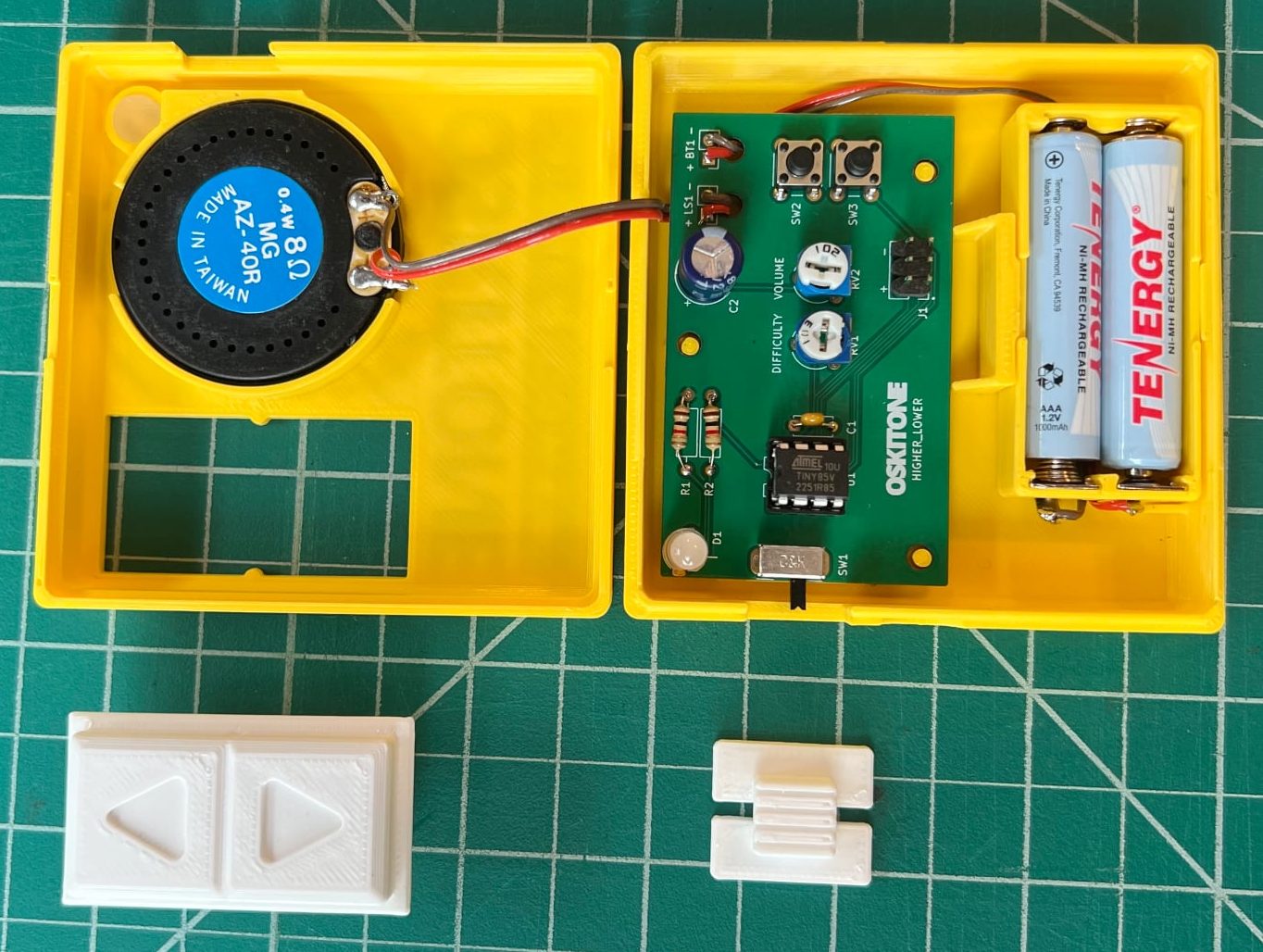
 There are only three chips inside: a CD4093 quad NAND with Schmitt-trigger inputs used as a relaxation oscillator, a CD4040 binary counter used as a prescaler, and a CD4017 decade counter responsible for spinning a signal around six LEDs while sound is generated, to represent an electronic die. Sound emerges from a speaker on the backside of the PCB, which we’re delighted to see is driven not by a separate amplifier chip, but by unused gates on the CD4093 acting as a simple but effective square wave booster.
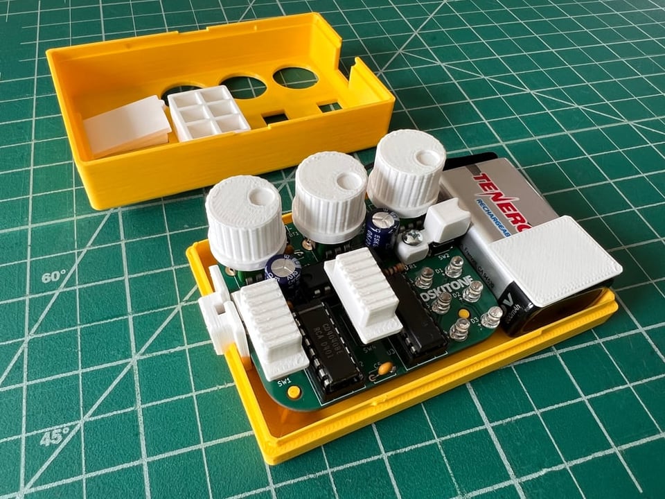
In addition, [Tommy] puts effort into minimizing part count and complexity, ensuring that physical assembly does not depend on separate fasteners or adhesives. We also like the way he uses a lever assembly to make the big activation button — mounted squarely above the 9 V battery — interface with a button on the PCB that is physically off to the side. The result is an enclosure that is compact and tidy.
We recommend checking out [Tommy]’s concise writeup on the design details of Space Dice for some great design insights, and take a look at the assembly guide to see for yourself the attention paid to making the process an educational one. We love the concept of presenting an evolving schematic diagram, which changes and fills out as each assembly step is performed and tested.
Watch it in action in a demo video, embedded just below. Space Dice is available for purchase but if you prefer to roll your own, all the design files and documentation are available online from the project’s GitHub repository.
Continue reading “Playful ‘Space Dice’ Kit Shows Off Clever Design”