Air Traffic Controllers use Automatic Dependent Surveillance-Broadcast (ADS-B) as an alternative to secondary radar to track aircraft. The ADS-B is transmitted by the aircraft and contains information such as GPS position, pressure, altitude, and callsign among other things at a 1090 MHz frequency, which can be decoded using any of a number of software tools.
[Mike Field] lives near an airport, and decided he wanted to peek into the tracking signals for fun. He turned to an RTL-based TV Dongle. Since the stock antenna was not cutting it, he decided to make one specifically for the 1090 MHz signal. His design is based on Coaxial Collinear Antenna for ADS-B Receiver by [Dusan Balara] which uses pieces of the coaxial cable cut to the right length. There are a number of calculations involved in determining the size of the cable, however, the hack in this design is the way he uses a USB based oscilloscope to measure the speed of RF waves inside the line in question.
We reached out to [Mike], and this is what he had to say. The idea is to use a cable of half the size of the wavelength which is calculated as
lambda = c/f
For the best reception, the sections of coax need to be half a wavelength long – but the wavelength of the signal inside the coax, which is shorter than the wavelength in free space. As this was a generic cable he had no idea of the dielectric that separates the core from the shield, so the ‘velocity factor’ could be anything depending on the exact composition.
To determine the speed of the signal in the cable, his approach omits the more expensive equipment. A length of coax acts as a stub – any energy that is sent into the cable reaches the far end of the transmission line and is then reflected back to the source. When the cable is 1/4th of the wavelength long, the reflected signal arrives back at the start of the signal 180 degrees out of phase – in a perfect world it would completely null out the input signal.

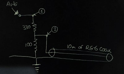
[Mike] starts his experiment with a 10m cable as he needs a test signal with a wavelength of 40m. In order to get the test signal into the cable, just two resistors at the back of a connector are all that was needed. The diagram shows the 330 ohms and 100 ohms in series with the center point at around 75 ohm which is a match for the cable.
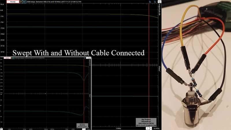
Using the Digilent Analog Discovery 2’s Network Analyzer the connector is swept from 1kHz to 10Mhz without the cable attached, and then with the cable attached. The dip at 5.666 MHz, caused by the reflected signal down the coax is very clearly seen. From there it is simple math – 40m/cycle * 5,666,000 cycles per second = 226,640,000 meters per second or 75.6% of the speed of light.
So the wavelength of the ADS-B signal is (226,640,000 m/s) / (1090,000,000 Hz) = 0.208m, and the desired length to cut is 104mm 1/2 wave elements and 52mm 1/4 wave elements and get soldering!
This is a great example of how a little bit of math and human ingenuity can be better than expensive test equipment and if you looking to get into software defined radios from scratch, start with Scratch.


You may mean pressure altitude (ADS-B also reports geometric altitude), but at any rate since I’m under a final approach path this might be an interesting things to tinker with – great article!
At one time I too lived under the approach of Purdue airport, with a flat gravel roof. I felt like putting a red light and a spray painted ” If you can read this sign you are flying too dam low” sign on the roof.
Alarm sounds if incoming is too low from data? Brace for…
The real trick is to be able to solder a joint in 1 second flat unless it’s Teflon, and then not around pet birds. A soldering gun will have the punch to do this on the heaver cable. If that cable is thin then an iron will do. At such high frequencies neat short stripping and joining makes it worth it.
I have wanted to make one about for 10 to 15 dB gain for FM listening when hanging out down at the crick in a valley. Shoot a line up a tree and haul up a single thing that don’t need aiming.
Epsilon_r ~= 1.8 then, too low to be teflon. I’m surprised.
What ever happened to the inexpensive time domain reflectometer – that’s what I used back in my third COOP internship with Rockwell Collins (“The Radio Company”) in Cedar Rapids, IA. I was in the lab working on a Small Mine Phone – a telephone system for use in underground mines that worked on twisted pair wiring. One of the old guys – I bet he was 50 or 60 at the time – I was probably 22 – suggested I order a Collins Receiver for use at my lab bench – I didn’t know why not, so I did. Well I hooked it up to a roof antenna and I couldn’t get a signal. So this guy tells me to order a Time domain reflectometer from test equipment. Well, a time domain reflectometer can tell you where anomalies are in a coaxial cable. So I got the time domain reflector, hooked it up to the coax that went to the antenna on the roof – then tried to figure out what was wrong. Well the time domain reflectometer told me the electrical distance from the time domain reflectometer where the problem was. Well now I needed permission from someone to go out on the roof to look for the problem. After I got permission, we took the reading from the TDR and guesstimated when on the roof the problem was. We followed the cable and at about the distance the TDR reported a problem, there was something wrong with the coax. We guessed it was a lightning strike that damaged the coax, so we cut out the bad portion, reconnected the rest of the coax.
Well what do you know, I could bring in a signal on the receiver. — Obviously – everyone wants to listen to stations like WWV
where you can tell the time to within seconds and other things. I am guessing the TDR was $1-2K in the mid 1970’s. Isn’t it wonderful what a nice piece of test equipment can do.
Hey, nothing bad to say about your measurement techniques, just thought you might like to know what happens in the Engineering world.
Scott Holland. web site: electronicscomputers20934240.wordpress.com