We recently featured an entertaining project here, a digital clock with a variety of different retro display technologies forming its numerals. Among those was an extremely unusual device, a rear-projection display with an array of bulbs each able to shine through a different letter or numeral slide. There was such interest in this device that its owner [Suedbunker] subjected one to a teardown for all to see.
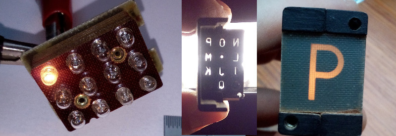
The displays came from an organ which he suggests may have been manufactured around 1900. We suspect that may be a rather early estimate due to its use of a printed circuit board, but it is no less a fascinating device for it. A rectangular enclosure secured by twist-tabs opens to reveal a matrix of small filament bulbs on a PCB and supported by a stack of resin boards, in front of which was placed a slide with a letter or number for each one. Before that lies a sheet of glass, and then a molded plastic lens assembly which provides an individual lens for each of the 12 bulbs. When a bulb is illuminated with these in place, the letter or number is projected on the screen at the front of the unit.
It has the advantage of simplicity, no need for a high voltage, and high-quality characters and flexibility in displaying alternatives through different slides, though at the expense of quite a bulky package. The bulbs are quite energy-sapping, so for his clock he replaced them with LEDs. We like it as one of the more practical retro numeric displays, but its size means we probably won’t see a comeback.
You can see our write-up of the clock using the projection display here.


These really lend themselves to be garage built. There’s only one special challenge, which is making the “sheet lens”. But maybe this could be done by making a silicone mold using ball bearings as the model, then casting acrylic resin in that.
Yes, bulk is definitely an issue, but hey, people make clocks out of CRTs, and those are even bulkier.
The real mystery about the unit [Suedbunker] disassembled is what application could possibly have needed the character set {I, J, K, L, M, N, O, P, Q, *}. It’s also a little curious, considering the cost of miniature lamps, that the display had all twelve lamps populated even though there were only ten characters in the mask.
All I could find even close to the character set is a paper on dia-7 vs dia-12 tonality.
https://sites.google.com/site/tolvtonalitet/7-turning-into-12
It claims the standard 7 keys use notes named A-G, and 12 key would be I-T skipping H all together.
Of course this display is missing the last three of those letters and contains a star instead, as you note there are in fact 12 bulbs populated.
Full disclosure: I know nothing of the subject of music notations, but as it took quite some google-fu to get from nothing to even that, I thought I’d toss it out here in the hopes someone else might expand on it.
Thanks, Dissy, you know, I didn’t even think about what the letters I-Q could mean in an organ, or in music in general. Of course, if you’re trying to indicate a note, you have to have 12 choices, and this set only gives us 9.
The letters may indicate something like which stop some other control is affecting, and they may have avoided letters A-G to avoid confusion with note names.
In any case, obviously the display is newer than early 20th century, so it was probably an upgrade done in the 1950s or 60s. If that helps any.
That sheet lens could be milled on any cheap CNC if you do a bit of polishing afterwards.
A “bit” of polishing? I don’t think you’ve polished any lenses from machined acrylic, lately. I’d much rather have it come out of a mold with an accurate curved surface that’s already glossy. The flat side I think maybe I could polish.
This one took just a few minutes, first 1200 grit sandpaper and then polishing paste:
http://essentialscrap.com/phone_closeup/on_phone-medium.jpg
It’s really quite fast and easy.
“We like it as one of the more practical retro numeric displays, but its size means we probably won’t see a comeback.”
Miniature DLP.
Can’t quite see how the aiming is done. the lenses all seem to be the same and in a regular grid and the bulbs are “aimed” by the mask. so is it just that the letters mask has slight perturbation of the regular grid so the letters are centered on the display at that focal length ?
Also – if the lenses are all the same – can you get a closer look ? Are they half rounds. I like the ballbearing idea for making a mold.
My guess is that the spacing between the lamps, then the masks, then the lenses are progressively smaller, so that the optical line from each filament through the center of its mask and the center of its lens goes through the center of the screen. It’s also possible that the flat sides of the lenses are slightly angled, but I can’t confirm or refute either of these by looking at the pictures.
I did find an exploded picture of one of the similar IEE displays: http://www.industrialalchemy.org/media2/pict13/projection340exploded.jpg
In this unit, there is first a set of condenser lenses, then the masks, which are arranged on a spherical surface, then the imaging lenses.
The IEE patent from 1960:
https://www.google.com/patents/US3041600
There’s also a Bell Labs patent for essentially the same thing:
https://www.google.com/patents/US2931027
I toured a mfg plant that made tiny incandescent bulbs for medical otoscopes (for eyes and ears). The bulbs were expensive because the filament shape and position were carefully positioned to produce a precisely centered point source of light picked up by the optics in the scope. I’m sure that in a similar way, special bulbs were part of these displays. Another interesting tidbit on the bulb process – after evacuating the air, each bulb was dipped in liquid nitrogen and a precise amount of xenon gas was admitted, which immediately condensed into a liquid at the tip of the bulb so they could then seal the bulb while retaining the xenon. I thought that was clever.
I remember seeing a ‘what’s new’ press release about ’62-’65 in a engineering zine that had these shown. I thought they weren’t as cool as the new Nixies.
1900 would predate the Telharmonium, that had slabs of slate and Bakelite as “circuit boards” with bussbars. Organ you say, current drawknob labels for organ console rebuilding include round e-ink “labels”. The label changes it’s stop’s name depending on organ emulation and language whilst looking like black-letter or fractur engraving, that uber goth font.
e-ink drawbar labels?! Now THAT is friggin sweet.
I worked on a military project in the mid ’70s that used these displays. There was another model in the same family that had a mechanism that would shift the film slightly so that you could have 24 different symbols.
I picked up a giant box of these, around 1987 or so, from a junk dealer in Cocoa Beach, FL that specialized in NASA surplus. Approx 2″ X 4″ on the front, about 6″ deep, used #44 bulbs. Never did come up with a project for them, and eventually gave them to my nephew.
An organ build around 1900 ?
These displays are *at least* about 50 years newer, they already use fiberglass PCB’s.
Nope. Only the front screen (diffuser) looks like a fibre-glass. The PCBs holding bulbs look more like phenolic resin based (FR-2?).
I had a couple of these in the 70s, which I purchased from the Honeywell Surplus Store on rt 9 in Framingham , MA. They were IEE brand, and came without any front covering (they were bolted to a translucent front panel?)
My guess is that the glass-fiber projection surface is a later addition. It’s a poor light transmitter, translucent plastic would have been a much better choice.
Yeah, the die casting and the lamps themselves put it in the 50’s at least. Plus the molded acrylic lens assy.
In fact looking at the teardown pics I would say probably 70s to 80s on construction. PCB backplane for the lamps and just general construction techniques.
I have one of these that is 0-9 plus I think + and -. I also have an even cooler meter movement that is a similar concept, the meter display is projected on a frosted screen.
Shadow Galvanometers are early tech from Leeds&Northrup,Rubicon,Sangamo and others were projection types. Also interesting are the fine tune displays put on on early fifties era radios like the RCA SRR-11/12/13 military units (and a couple of period signal generators).
First step in replicating these would be to make a silicone mold and a clear urethane casting of the lens array, both under pressure so there’s no bubbles.
Swap the replica lens array into the original display to verify it works.
To see what effect the lenses have on the light, mount a small laser to a support, shining through a hole. Move the lens array around to shine the laser beam through each lens and see how it deflects.
Here’s another interesting rear-projection display: http://www.decadecounter.com/vta/articleview.php?item=626. This one also uses an array of incandescent lamps, but it uses what they call a “sphericular” lens (i.e., like a lenticular screen, but in two dimensions) that illuminates a single mask that does all of the characters. I’m finding it difficult to describe how this works, so here’s the patent for it: https://www.google.com/patents/US2981140, which goes into great detail.