We’re all too spoiled nowadays with our comfortable ways to erase and write data to persistent memory, whether it’s our microcontroller’s internal flash or some external EEPROM. Admittedly, those memory technologies aren’t exactly new, but they stem from a time when their predecessors had to bathe under ultraviolet light in order to make space for something new. [Taylor Schweizer] recently came across some of these quartz-window decorated chips, and was curious to find out what is stored in them. Inspired by the BIOS reverse engineering scene in Halt and Catch Fire, he ended up building his own simple reader to display the EPROM’s content.
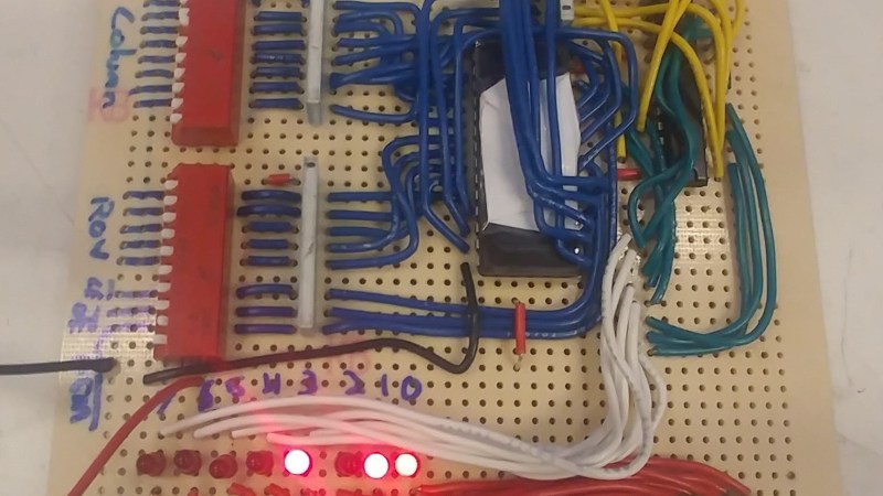
The 2732 he uses is a standard EPROM with 32kbit memory. Two pins, Chip Enable and Output Enable, serve as main control interface, while 12 address pins select the data stored in the chip’s internal 4K x 8 arrangement, to output it on the 8 data output pins. You could of course hook up the EPROM to a microcontroller and send what you read via serial line, but [Taylor] opted for a more hands-on approach that lets him read out the data in a manual way. He simply uses a bank of DIP switches to set the address and control pins, and added a row of LEDs as display.
As you can see from the short demonstration in the video after the break, reading out the entire EPROM would be a rather tedious task this way. If you do have more serious intentions to read out the content, you could have a look at one of those microcontroller based solutions sending data via serial line after all.


Use hexadecimal encoding wheels :-)
Oh and I created several hex=>7seg displays, the latest using bare diode ROMs and Numitrons ! :D
https://hackaday.io/project/26068
https://www.youtube.com/watch?v=KEEPjxJPWQ0
Ooo, neat. What are those leds you are using?
He say that they are called AL102, Russian LEDs apparently
Back then, we used EPROMs salvaged from old computer PCBs to generate light effects.
Add an oscillator, a counter, and some optocouplers and triacs, and you have cheap disco lights.
Some EPROMs had interesting patterns at certain addresses.
Advanced tinkerers erased the EPROMs (sometimes using the sun) and programmed their own patterns byte by byte, using DIP switches.
Problem: One single mistake, and you have to start over.
I’m reminded of a (~30 year old) design of mine (at least I think it was mine, it might have been a co-workers) that implemented a Finite State Machine using an EPROM and a couple of 74xx374 octal flip flops. Basically the data output of the EPROM defines the state, and the inputs and the EPROM data output (the current state) are fed (via the FF) back to the EPROM address inputs.
I had always thought of EPROMs as just being static lookup tables. So I was rather surprised to find that EPROMs perform self-timed reads. Basically they have a transition detector on the address and control inputs. When any of these inputs changes, the EPROM wakes up, starts a read cycle, latches the output data then goes back to sleep.
This isn’t clearly spelled out in the datasheet. I think there might have been a footnote on page 17 in a 6 point font or something. There was also a timing diagram that showed VCC current vs input signals which indicated the same thing.
The problem for my design was that at initial power on, if VCC rose at a particular rate, the transition detector wouldn’t fire and the EPROM would output data that didn’t reflect the memory content at the address on the address inputs.
The fix was to use a brown out detector to toggle the chip select input once VCC was stable.
Harry Lythal SM0VPO also did something similar with EPROM’s:
http://213.114.131.21/eprom/e-pla-00.htm
i did many project with eprom this way in school, because cpld was not heard of :) also there was no microcontroller, so the eprom was the coolest of the logic ics, my eprom programmer was attached to my zx spectrum :)
Built my first programmer using SPST switches, and a few support parts. This brings back memories…Now, I just have to erase the EPROMs I have and try something new. ;)
been there done that. With 74188 32 byte PROMs used in many arcade machines from the late 70s and early 80s.
This is what I was looking for. I need to get the code from a 2Kx8 PROM. My idea is to use two 74LS47’s to drive a two-digit LED display (I have these in my target project from the 1980’s), and what I have on hand – DIP switches – to set the address. Back in the 80’s at GE we had a bunch of encoder thumbwheels. I don’t have any of those. I was about to purchase an old programmer that could read in the data, but this is a one-off need.