Some time before experimenting with MRI machines and building his own CT scanner, [Peter Jansen] wanted to visualize magnetic fields. One of his small side projects is building tricoders — pocket sensor suites that image everything — and after playing around with the magnetometer function on his Roddenberry-endorsed tool, he decided he had to have a way to visualize magnetic fields. After some work, he has the tools to do it at thousands of frames per second. It’s a video camera for magnetic fields, pushing the boundaries of both magnetic imaging technology and the definition of the word ‘camera’.
When we last looked at [Peter]’s Hall effect camera, the device worked, but it wasn’t necessarily complete. The original design used I2C I/O multiplexers for addressing each individual ‘pixel’ of the Hall effect array, limiting the ‘framerate’ of the ‘camera’ to somewhere around 30 Hz. While this would work for visualizing static magnetic fields, the more interesting magnetic fields around us are oscillating — think motors and transformers and such. A much faster magnetic camera was needed, and that’s what [Peter] set out to build.
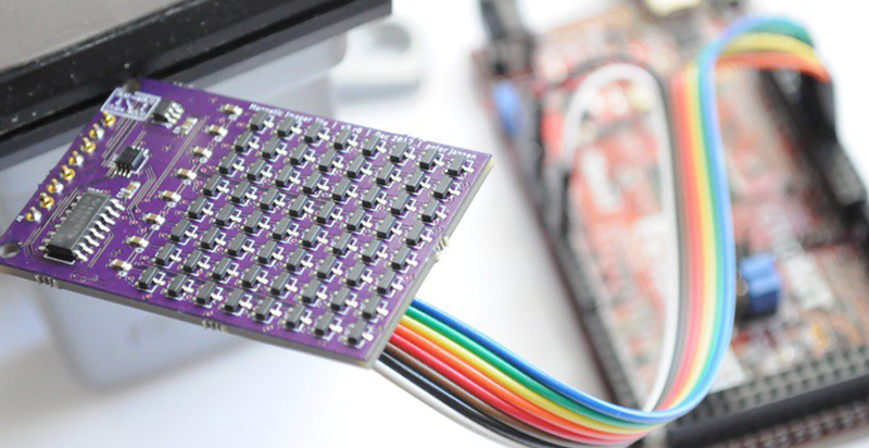
Instead of an I/O expander, [Peter] re-engineered his design to use analog multiplexers and a binary counter to cycle through each pixel, one at a time. Basically, the new circuit uses two analog muxes for the columns and rows of the Hall effect array, a binary counter to cycle through each pixel at Megahertz speed, and a fast ADC to read each value. It is, bizarrely, the 1970s way of doing things; these are simple chips, and the controller (a Chipkit Max32) only needs to read a single analog value and clock the binary counter really fast.
With the new design, [Peter] is able to get extremely fast frame rates of about 2,000 Hz. That’s fast enough for some beautiful visualizations of spinning motors and transformers, seen in the video below. Further improvements may include three-axis magnetometers, which should allow for some spectacular visualizations similar to [Ted Yapo]’s 3D magnetic field scanner.


Pretty damn cool!
Yeah, that’s very cool.
neat!
That would be a nice way to visualize electric fields, if it can detect them :)
For that, you just need an array of capacitive sensing plates. As in it might be worth looking at hacking a smartphone touchscreen.
Yes. I was wondering the same thing. Can you, for instance, put this up against your wall and see any field generated by AC wiring? I’m sure you’d need to load the circuit (since a circuit without a load tis no circuit at all and current must flow for an electromagnetic field to be present), but it would be interesting to see.
For sense mains power through a wall, maybe something closer to a single coil guitar pickup. They are aggravatingly sensitive to mains hum.
Just noticed the tag on this post (and a couple of others)! Took me a second to make the connection. Very clever Brian!
This is how the video industry got started. Can you imagine a hand held camera that can generate a picture of magnetic fields. I know there are satellites that look at the earth that do the same thing but it would be hard to put a satellite in your pocket.
My turn to be _that_guy_ again… it’s “tricorder” (probably a simple typo). (/nitpick)
I think that innovations like this are the next generation for medicine where basic analysis is performed at home using simple, low cost devices providing analytical data to doctors located somewhere in the cloud. Maybe one day, the doctors will be virtual as well?
Innovation will save our planet, not more bureaucrats and more laws and more regulations…
Regulations, however, do go a long way towards helping preserve what we have. Innovation is fine, but setting limits on destructive practices is going to have a significant impact.
Instinctual to rebel against “no” regardless of whom’s doing it. Progress isn’t “no”, it’s the promise of cookies, cake, and ice cream, no matter what overindulgence may bring.
Regulation is the “Do not put poison in your cookies, cake, and ice cream and wash your hands before baking them”
The idea that progress is hindered by saying “Don’t cross this line” is a fallacy. We had to put those lines/regulations there because companies and people crossed them, got people killed/poisoned, and then proceeded to shrug and ignore the consequences.
I don’t think your argument has much of a leg to stand on. To be clear, you are saying that all regulations are cut and dried and none of them are ever made for less than noble reasons.
Agree with Capt. For example, in medicine (the narrow field I was referring to with my “more regulations” comment), costs are driven skyward by over regulation and by malpractice avoidance where more is done than necessary because someone sued someone else because (hyperbolic) “they were examining his eyes and missed the parasite on his butt” type of lawsuits.
“whom’s” -> https://en.wikipedia.org/wiki/Hypercorrection
Focusing mechanism?
It’s a good question. Since the fields radiate radially from objects, I’m not sure what a focusing mechanism would look like (or, if it’s possible) — but maybe someone with more E&M background than me could weigh in?
As far as I’m aware, it’s impossible to coherently focus a magnetic or electric field. You can concentrate them, but you’d lose the “image” and just end up with an average value.
ligth is electromagnetic waves, the problem is resolution is related to the frequency
Metamaterial lens, or even a simple dielectric lens.
One may focus radiation, but one may not “focus” an image of a remote field.
Either you gather/distort the field itself in which case you’re not imaging it, or there must be something (radiation!) emitted by the field that you focus in order to gather the image.
A 3D one of these would be cool.
That’s so neat
He needs to make another board, turn it upside-down, and place it on top of the first so that the Hall effect sensors mesh together in the gaps between each other. Expand the sensing routine to use the two boards, and you’ve got 2x resolution.
That’s a neat idea, but because the field intensity falls off so quickly, unless you were looking at very large fields it would prevent having the object close/touching the surface. For large fields (like rare earth magnets), these can be sensed from several inches away, but for the small fields that are likely to be more interesting (like the fan motors in the video) it really needs to be directly interfacing for the best views. The ~5mm board height (with components on both sides) would likely reduce most of that signal for a sandwich configuration.
Now THIS is a hack! Great job!
Time to make some Jordee glasses liked on star trek. Actually, thinking…those would never work as portrayed. You’d have to put your glasses close to anything you wanted to see.
Why had this never been done before?!
It has, on a chip. I don’t think the 2D array version ever made it to market though. Linear versions have but are not optimized as to be applicable for this.
http://ieeexplore.ieee.org/document/5969355/
That being said, this is still an astonishingly cool hack of the highest order.
Very cool!
What would be astoundingly gratifying would be to have a chip manufacturer produce this as a single-chip device (Hall effect sensor grid on a single chip). I think the applications would be found very quickly (machinery diagnostics, security work, modest-level tomography etc.) once this was done.
Remembering back to the dark ages when people rolled their own CCD cameras out of EEPROM chips, is there any possibility of using the semiconductor grid in an existing memory chip this way?
“on a single chip” implies it is very small and therefore useful for fields where the total interesting structure is much less than a mm across, and the resolution is perhaps in microns.
This, at human-scale, is much more useful.
Hint: you can’t make a lens for this as we’re not observing propagating radiation, but a field.
Yeah, this definitely deserved a full post instead of just a mention in the most recent weekly Hackaday Links.
It’s a redesign and significantly more useful now. I was interested.
I was thinking “seen this before”, but this is a significant improvement! And interesting, in it’s way, that he went back to analogue to do it. Did his first version use I2C Hall Effect sensors, and this one uses analogue ones? That’s the way I imagine it, if he was multiplexing the I2C. Ultimately limited by I2C’s data rate, then.
He might have run, perhaps, a whole row in parallel, and maybe bit-banged I2C out of 8 pins at once, to read in a whole column at a time. The software would be a pain in the arse though. And would only have octupled his frame rate, not 100xd it (more or less). So Hall Effect devices react pretty instantly then? I suppose cos they’re basically electrons running down a thin tube, it’d be instantaneous to react. The electrons themselves are the moving, changing part, not much inertia there.
Impressive too the analogue switches work at 1MHz. Again, no capacitance or whatever slowing them down. Nice bit of work from the analogue chaps at the chip factory. Also good that if fits down the (USB?) pipe to the computer.
This is nice! I wonder if he could give it a higher resolution? Just by shoving the sensors in tighter is the only method I can think of.
Would be interesting if he could alter the frame rate, have it sort-of accumulate the value for each pixel, per frame, like a camera or eye does. I suppose you could do that in software. Would be nice because you could catch very quick events and slow them down.
Clever! And even better, he actually found practical uses for it! Surely the ultimate challenge.
excellent – surely there is some HD competition this can be submitted for, if not there needs to be :-)
Augmented reality, machine vision, sensory enhancement/replacement..
A nice idea would be to try hacking a MEMs mirror array from a cheap projector…
If you have access to the bare array of pixels at an analog level, you would be able to use the individual pixels as capacitor plates and achieve high resolution, high speed imaging…
A relatively easy experiment would be to use such a MEMs mirror array powered on with a UV laser pointed at it, and measure fringe patterns with a high resolution camera
“Kenneth wheeler; Discovering the missing secrets of magnetism.” Download it for free off archive.org This will explode you mind into billions of fractal little brain fragments. A powerful arming read. I am not affiliated with the author just a grateful and admiring fan.
SOOO COOOL! definitely gonna use this some day
So if one could spin the sensor package without tainting the field the resolution could be extended. Plus it might make the tricorder warble sound.
That’s brilliant. Put the array opposite a coin cell, an arduino on board, and stream the data with an NRF module. Optical gate on the back for sync.
You would need to keep it physically separated from your target as well, which could reduce signal strength, but you could also stagger the modules and offset them in the time domain for greater resolution.
Start with one of those light up spinning toys and you have power at least via the wipers so no coin cell.
Can you comment on the dynamic range of the detected magnetic field?
Would it be possible to have a multi-range detector array, up to 1.5T, 3T or even above?