We shouldn’t laugh, but we know the feeling very well. [Gear Down for What] invented a revolutionary transmission and fabricated it from scrap material when he was 16. Except he later found out the same design was the subject of a patent filed 14 years earlier. Dismayed he destroyed his prototype, but fast forward to today and he’s made a 3D model of a ratcheting continuously variable transmission. You can see a video of him explaining how it works below and put your own spin on the idea by grabbing the model from Thingiverse.
The model is just for demonstration purposes. We doubt it would wear well enough to use in practice but it’s great to get your hands on for a really intuitive understanding of the mechanism. Some modern automobiles use a continuously variable transmissions (CVT) and many recreational vehicles and motorcycles use them. Like any transmission, their job is to match the motor’s rotation to needed output torque and speed by offering different gearing ratios. Whereas a normal transmission provides a few fixed gears, a CVT changes seamlessly through a range of ratios.
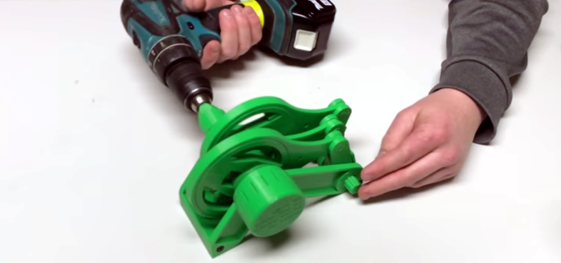
Some of the design of the transmission is pretty tricky, like the cam adjustment. The video shows the rationale for how the design works and how it relates to tank steering (tank as in an Army tank; not like a gas tank). The model isn’t just plastic. It uses some screws and BBs, as well. However, if you have a 3D printer and wanted a good classroom demonstration, this is the ticket.
We’ve seen other geared variable transmissions for robots before. The planetary gears in the cam adjustment of this design are well understood. If you want to brush up your planetary knowledge, there’s no time like the present.


Sure, that’s clever, and I encourage you!
But as far as I understand it, the transmission of power to the output axis is done by ratchets, and the part of the ratchet resting on the splines of the axis is animated by a relative movement with respect to this output axis, at all phases of the cycle. And unfortunately, this inevitable friction is also carried out under high pressure.
This is undoubtedly the Achilles heel of your concept: there will be inevitable high wear and tear.
Current transmissions use gears that run on top of each other without relative slippage. This is what makes wear and tear manageable.
Translated with http://www.DeepL.com/Translator
Completely off topic, but did you edit any of the text you pasted from DeepL? It reads really well, I couldn’t tell it was translated from French (presumably?). Thanks for the link, I shall use this in the future :-)
—
Complètement hors sujet, mais avez-vous modifié le texte que vous avez collé de DeepL? Il se lit très bien, je ne pouvais pas dire qu’il a été traduit du français (vraisemblablement?). Merci pour le lien, je l’utiliserai dans le futur: -)
Aucune modification depuis la traduction de DeepL !
DeepL.com me change la vie ! Très recommandé !
I’m with you! I couldn’t figure out at first why there was a “Translated by” mention. Outstanding.
> Current transmissions use gears
They aren’t CVT though.
You’re absolutely right. There have been many CVT systems on offer. For fundamental physical reasons, all of them necessarily have some form of friction in their operation.
In my opinion, what gives a practical interest to this or that CVT technology is precisely the way in which wear parts, their replacement, etc. are managed….
Great job, I like the idea!
But, could we call it a CVT as long as the output axis is moving step by step? I mean, it is not really a continuous movement, even if at high speed, the steps are so small that we can assume it is nearly continuous. The “steps” would inevitably be converted in some kind of vibration, right?
It’s continuously variable, not continous transmission. Motion is not continuous, but ratio is.
It can only turn the output shaft at ratios which correspond to full clicks of the ratchet, so the ratio of the mechanism is a stepped function, not continuous.
For the cam ratios which do not match the ratchet steps, the mechanism simply slides back, so you can only get certain numbers of clicks per revolution, and therefore only certain average input/output speed ratios are possible.
Agreed, because this is a ratchet and pawl mechanism, this is not truly continuously _variable_. If the ratchet teeth are say, 10 degrees apart, adjusting the cam for 9 degrees more motion does not make the mechanism engage the next tooth, thus no change. Carefully measured, this mechanism will produce discrete steps of gear ratio.
That said, there are other ratchet mechanisms that this could be designed around that do not have that limitation. “sprag clutch” is a good place to start.
If you are powering this with a piston engine, is that really continuous motion? When I load my truck up and take it up a steep hill, I can feel each cylinder firing. If you want continuous motion I think you need to go to a turbine engine. On the transmission perhaps a free wheeling flywheel would help. The thing I did not hear in the video was the low and high ratio of the transmission.
Are you sure about that?
If your engine is turning at 1200 rpm your crankshaft is turning at 20 Hz, and if you got six cylinders each firing in sequence every other turn, the piston firing frequency is 60 Hz which is not felt or heard as individual pulses because it’s too fast.
If you’ve got distinct pulses going on, it’s likely that one of the pistons is misfiring under load, or there’s a mechanical resonance that makes the transmission shake around.
Would it be possible to use a crankshaft instead of the ratchets, to reduice the friction?
And thinking about it, but could you use this idea to make a variable crankshaft?
> could you use this idea to make a variable crankshaft?
Technically yes. But a) why? and b) it wouldn’t bring the benefits you think it will.
Compression ratio will differ, cylinder filling will be seriously off (exhaust gas will stay in there and not be pushed out), more power will be required to actually rotate the crankshaft when it’s close to the centre, you’ll have loads of additional moving parts, the crankshaft overall will be weaker because it’s not a solid piece, conrods will also be weaker because of the slot for the offset gearing and so on.
Actually there are some companies that are building this kind of variable crankshaft for the explicit purpose of changing the compression ratio, and thus optimizing the motor efficiency to various load situations: http://waulis.com/
Interesting concept – might actually be possible to build that with low’ish friction in mind (in an oil bath?). I wouldn’t call the concept continuous however. There will always be a “output axle ratchet clicks 3 or 4 or 5 or ..” times per input-wheel revolution. Any push of one of the crank rods set in between will push the axle not far enough to do the next click.
It’s continuously variable transmission, not variable continuous transmission ;)
Only is you actually used ratchets. Perhaps you could use sprag clutches instead (like most motorcycle starter clutches and such), which can engage in any position. Also, this might be more wear resistant than the ratchets, assuming they are properly lubricated, but probably harder to do with regular 3D printing.
The output of each of the cranks will be a sinusoid; thus three of them, with half-wave rectification (only one direction is used) will give an output shaft speed similar to a 3-phase half-wave rectifier. Considering the analog to an electrical system, full-wave rectification would be a huge improvement, but not exactly trivial to do. I think you’d have to have a second ratchet per crank, concentric with the first, with the ratchet in the opposite direction, and a gear to reverse the direction and couple to the main output shaft. Hugely complicated, it would probably be easier to just have a second connecting rod on each crankshaft lobe, mirrored to the first (so at the bottom of the device).
The crankshaft adjustment system seems like another weak point to me, but it doesn’t need to move much, so it’s mostly the strength of the gear teeth and hammering because of play than actual wear what would concern me. I wonder if that could be done with some kind of worm gear or spindle drive instead, which would dramatically reduce the load on the differential gearbox used for adjustment.
Maybe if you didn’t use passive ratchets or sprag clutches (which are like diodes), but some kind of controlled devices that can transmit torque in either direction (like MOSFETs), you could make the whole thing reversible, by going past the neutral setting.
I have to say, the whole thing is very clever, and even more amazing for a 16-year old! I don’t think it’s going to revolutionize the automotive industry (drivetrain electrification will make CVTs obsolete, I think), but that doesn’t mean it won’t have other niche applications, and a mind that can come up with this can certainly solve many other engineering challenges!
First things first. To fully understand the challenges associated with CVTs, start by going to Google “PTE April 2013” and clicking on the first 2 pages under “Departments”.
Comments/questions are welcomed.
This is John Pellegrino again. On March 13, I posted a comment regarding your article on a 3D printed ratchet style type of CVT.
In that comment, I INCORRECTLY quoted a website address that is the basis of my comment.
The CORRECT website address is “Power Transmission Engineering 2013” and clicking on the first two pages.under “Departments”.
My sincerest apology for any inconvenience that this may have created.
I had plans to build a gokart with this sort of transmission except using spur bearings instead of a ratchet. Had some clever reversing linkages if I remember correctly.
The idea of having a variable-throw crankshaft occurred to me decades ago. However, I couldn’t figure out a good way to take the resulting variable reciprocal motion and convert it nicely into variable speed rotation. The idea of using ratchets occurred to me, but I didn’t like it, and I didn’t follow up on the idea much. What I liked about the idea in general is that if the throw is 0, you’ve got an idle position, and therefore you don’t need a clutch for idling.
What about replacing the ratchet shaft and levers with a three throw crankshaft, with the throws 120 degrees apart?
Things this design does not have. 1. Output reversing. A reverse gear is essential for a wheeled vehicle transmission. 2. Coasting or freewheeling. Set it to neutral and vehicle motion would spin the ratchet shaft. It would be impossible to push the vehicle backwards. 3. Engine braking. The engine resisting torque input to its crankshaft is used to prevent a vehicle from running away when coasting downhill with the engine at idle.
This should be sold as a continuous Variable valve lift mechanism, most companies want to go camless drives currently and looking camless alternatives, if this can become very efficient by reducing friction, just eliminate the output shaft and put some rollers or create something @ the end to actuate the valve lift and degree and wadah and very efficient camless drive for automotive engines.
Nice patent by the way I always thought how you thought I would like to make a patent what the world would use
So this device (or something meaningfully equivalent) was invented in the 50’s for making variable windshield wiper speed before the advent of the intermittent wiper. I happen to have one of those drives apart for a complete rebuild, and the slipping one way clutch mechanism on the output shaft, combined with the 8 fingers transferring power on sequentially indexed cam positions gives it an incredibly smooth operation. That smooth operation is necessary since that particular drive is what gives me infinitely variable speed on the powerfeed to my mill table. They have a point and not all CVTs need to run a car down the road. Also, on these the speed selection is done by moving an arm rather than a click-stop mechanism which makes it more of a “continuously” CVT.
https://www.zero-max.com/cd-adjustable-speed-drives
https://patents.google.com/patent/US2691896A