If you’re populating kits, it can get tiring and time consuming. Like all good repetitive processes, it should be automated. As far as cutting resistors goes, this is one way to do it, thanks to [Pablo].
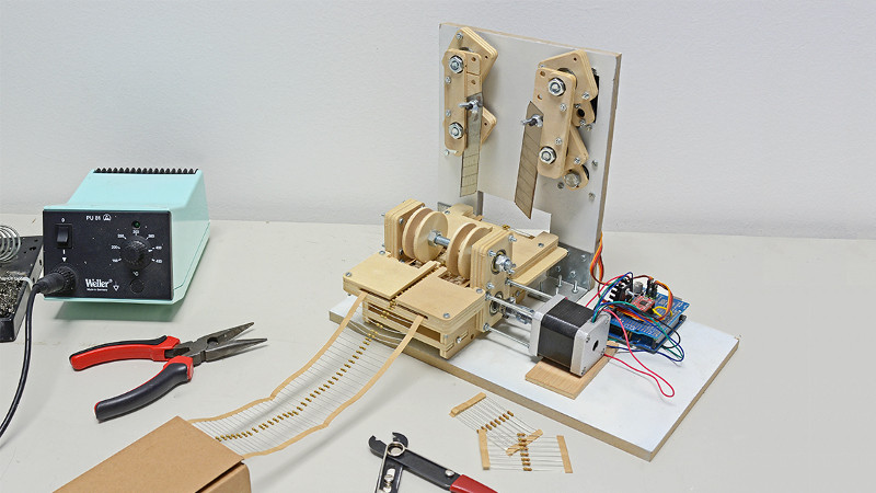
The build is actually cribbed from earlier work by a gang called [oomlout]. Parts for these cutters are made with either lasercut or CNC milled sheet stock. A stepper motor is used to transport the resistor tape, and the cutting blades are moved by standard hobby servos. The use of servos for the blades allows the action to be controlled precisely without having to go to the effort of implementing extra limit switches and circuitry.
Control is by an Arduino Uno, with an A4988 driver controlling the stepper. Servo control is achieved with the Uno’s onboard peripherals. There’s a video below of the machine in operation, which shows it to be a simple and efficient tool for the job.
This build turns an otherwise maddeningly basic chore into a set-and-forget operation. We’ve seen other work in this area before from the [oomlout] team, too. Video after the break.
[via oomlout]


Someone just asked in Friday’s Hack Chat how many open source projects get replicated. I think this is a perfect example of what kinds of things should be replicated.
You’d have to cut a bazillion resistor tapes to get back the time put into designing, building, and documenting this gorgeous machine. But if other people implement your design as has been done here, that multiplies the effort through the ecosystem. If oomlout ends up using someone else’s design for another specialized machine, you could say the time is then recouped through the ecosystem as well.
I love this!
Maybe not a bazillion. How much of a loss would you suffer if you got carpal tunnel syndrome from hand counting and cutting? Your quality of life will go down hard.
I’d rather waste time reinventing machine to do the job and spare my health from various repetitive injuries.
There are simpler rigs where you just push the ribbon to a stop and use a regular paper guillotine to cut it.
A person can go through the whole reel in minutes. I know because I used to work as a temp in an electronics fab and that’s exactly what we did: cut components off the reels for assembly, bend the legs etc. by hand, and this was Nokia-Siemens instead of some chinese sweatshop.
Instead of the “reach.around”, the cut resistors should land on a conveyor belt which transports them back to the front of the machine.
Who uses through hole resistors anymore on new designs?
People making DIY kits.
like this project, that does not use a single through hole resistor !
I prefer dip and through hole if I can.
I’m not a great fan of trying to position what equates to grains of sand. I shake a lot at the best of times. Far too much to contemplate smd.
Wrapping wire around a couple of blocks, gluing it in place and cutting all the loops apart, sand down the other edge and squish the smd chip between them.
A bit like the rubber connectors you get on liquid crystal displays. Fiddly but gets the job done for most things.
Know of a breadboard that will take SMD resistors? One universal and can work with 52,872 different size and shapes of common SMD resistors, capacitors, transistors, and ICs?
Kit building is still a huge hobby.
For prototyping on a breadboard, yes, but when it leaves the breadboard and lands on PCB I prefer SMD components. It saves drilling holes too :) Soldering smd components is a little bit quicker and easier to me personally.
Also anybody who prototypes using wire wrap before designing PCBs. For example I don’t have permission from cahabitants for home chemistry and what I want to build right now is too large to iterate a design cheaply via board house. So until I have at least a tested netlist I’m using perfboard, wire wrap sockets, and long .1″ headers. I still don’t need to build kits of that, but surface mount parts are often harder to hand solder so i understand their use there.
ingenious to say the least, at my job we use a lot of thru hole component, but slowly we move to smt pcbs ….