Experience — or at least education — often makes a big difference to having a successful project. For example, if you didn’t think about it much, you might think it is simple to control the temperature of something that is heating. Just turn on the heater if it is cold and turn it off when you hit the right temperature, right? That is one approach — sometimes known as bang-bang — but you’ll find there a lot of issues with that approach. Best practice is to use a PID or Proportional/Integral/Derivative control. [Electronoob] has a good tutorial about how to pull this off with an Arduino. You can also see a video, below.
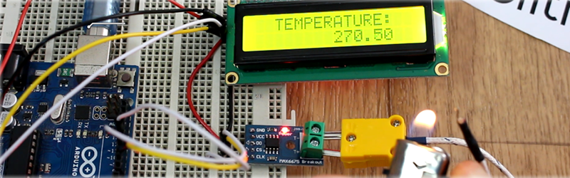
The demo uses a 3D printer hot end, a thermocouple, a MAX6675 that reads the thermocouple, and an Arduino. There’s also an LCD display and a FET to control the heater.
The idea behind a PID controller is that you measure the difference between the current temperature and the desired temperature known as the setpoint. The proportional gain tells you how much output occurs due to that difference. So if the setpoint is way off, the proportional term will generate a lot of output to the heater. If it is close, only a little bit of output will result. This helps prevent overshoot where the temperature goes too high and has to come back down.
The integral term adds a little bit to the output based on the cumulative error over time. The derivative term reacts to changes in the temperature difference. For example, if something external causes the temperature to drop suddenly, the derivative term can goose the output to compensate.
However, the operative word is “can.” Part of setting up a PID is finding the coefficients for each term which for some systems could be zero or even negative (indicating a reverse effect). There are a lot of other subtleties, too, like what happens if the output stops affecting the temperature for a long period and the integral amount grows to unmanageable magnitude.
By the way, we’ve covered a PID library for Arduino before. While this post talks about temperature, PID control is used for everything from flight control to levitation.


ehmmm… temperature control by modulating the heater element in the correct way is one thing… but measuring the temperature is another.
When a thermistor tells you that you project is exactly 100C you are not done. Because this doesn’t mean that the whole block is heated up to 100C, the block ins’t perfectly insulated, there are losses and in case of an extruder, the plastic it is being fed will cool down the block locally. Also the thermistor needs to make propper contact with the block, a glass beat thermistor isn’t perfect. As glass is a thermal insulator, although the glass is thin it does create an error or lag. Also how how does the heat energy propagate through the block itself, the accuracy of the thermistor (and the way you read it and calculate it) is of course important but that’s for another time. A thermal couple with a dedicated IC is therefore much better but could introduce problems in some cases as the tip of the thermal couple is electrically conductive and could require some additional insulation, creation the same problem again.
Anyway, there are many things that can go wrong, modulating the element using a PID algorithm is great but only a small part of proper temperature control. But then again it all comes down to how accurate you really want it to be.
Therefore in many cases… the bang-bang approach is certainly far from perfect, but in most cases it’s more then good enough.
PS: nice video, nice article, PID is certainly the way to go, but use it wisely.
Industry have used PID for decades – you are correct about the lag etc. but in industry, a certain level of pragmatism is required so we accept that there is a lag and either tune the loop accordingly or change the system by having another loop connected to the item under temperature control or some form of dummy block which is analagous to the thing you are trying to heat.
Some systems do both at the same time – they will control the heating power by a primary loop and monitor the rate of temperature rise (or fall) of the component in the furnace then pull back the heating primary loop as required to avoid overshoot.
We deal with accuracy through regular calibration checks using a primary or secondary standard instrument which is solely used for calibration never control.
It have nothing to do with PID..
> A thermal couple with a dedicated IC is therefore much better
Thermocouples aren’t very accurate either, plus you get additional problems trying to measure the cold junction temperature.
> Thermocouples aren’t very accurate either
That’s a very general statement to a very broad topic with some very specific intricacies.
Perhaps I took a little too short turn there. What I really meant was that with a thermal couple IC you don’t have to worry about calculations IF you choose the correct type of couple to be used with the dedicated IC. Of course you still need to know what you are doing, but it can be much easier as the some of these IC’s can solve many of your problems. I should choose my words more wisely (or to be more precise, I should know when to shut up, I guess, haha)
And the derivative part of PID is?
Never mind I glazed right over the D reverence. Good write-up, and I just read the article. Next he needs an auto-tune function to calculate the initial P,I,D values.
Talking about simple on-off-on control, are there any commercial microwave ovens that don’t use that method to control output?
And if so, what method do those more fancy ones use? I know it’s hard to control so I wonder if anybody tried.
Note that a microwave has no closed-loop control; it only turns its radiator on only part of the time to change the output power.
First challenge in MW closed loop control would be temperature measurement without frying the sensor:-)
Intriguingly, other things are used instead – a moisture sensor in the fan exhaust to measure steam generated is common. There are fiber-optic temperature sensors that don’t have the induction problems that the usual methods use, but they’re prohibitively expensive for consumer level appliances.
Interesting, the moisture measurement will provide an average measurement without local effects
I had a microwave oven with a temperature sensor probe. I think they stopped making them as a cost savings. It just had a shielded cable to the probe. It’s easier than a regular oven because the jacket isn’t subject to radiated heat.
Cavity magnetron based ovens only do this because magnetrons only work “on” – there’s no half-power setting that wouldn’t drive the cost of the (very simple) internal circuitry enormously high. “Off and on” through timed duty cycles is the traditional, economical way around that.
Ovens with solid state emitters are being test-marketed and seem to be economically competitive and offer the advantage of emitter array modulation so this may change (and possibly rapidly as the device cost/simplicity could possibly drop). Of course you have the usual food loonies that think microwave ovens magically transmit bad juju into their soy milk but that can’t be helped.
Here’s a pretty good article on the changes in the wind:
http://www.mwrf.com/industrial/will-today-s-microwave-oven-soon-be-thing-past-part-2
>”By eliminating the rotating platters common to magnetron-based microwave ovens, system reliability is further increased due to the reduction of mechanical moving parts”
The rotating platter in a microwave oven isn’t strictly necessary anyways, but it serves an important point that they haven’t addressed. The glass serves as a dummy load inside the resonant cavity, preventing the resonance from growing out of bounds when there’s little or no other absorbing materials in the microwave, thus preventing the reflected energy from burning out the RF source.
There have been a number of microwaves where the platter doesn’t rotate, but instead there’s a rotating reflector behind a RF-transparent panel – built on the same axle as the cooling fan to save on mechanical complexity.
Consumers didn’t buy these models because they didn’t trust the food to cook evenly unless they saw it spinning around inside. No matter how you make a microwave oven, the 2.43 GHz radiation is absorbed within 2-7 mm in typical foodstuffs, so it’s going to be burning hot in places and cold in the middle anyhow.
Ironically, ice absorbs 2.43 GHz RF so poorly that trying to melt an ice cube in the microwave oven will heat only the plate.
Amazed me when I first started working with spectroscopy how uniquely the same chemical formula of different polymorphs (phase, crystal structure, isomer (which is more obvious)) can behave at different frequencies.
Quite possibly Panasonic Inverter Microwave Ovens
https://youtu.be/MOq5qreg1zg
Seems like other than I’m guessing an induction heater portion of the circuit and some other components… those microwave ovens have better components for communications systems if not noisy. Wondering what those are like tore down and can be hacked from the components? Thanks for sharing.
This is a great learning exercise but remember that you can get a complete PID controller, thermocouple, SSR and heatsink for less than $20 from AliExpress. We used a lot of these where I used to work. We always included a second controller to monitor the first. It seems that when SSRs fail they like to fail in the on state. The second controller killed the power to the project if the temp got too high.
Or better yet get a name brand used one off ebay for about the same price. They are so much better than the cheap chinese ones.
PID far too over complicated IMO ….. I’d program the Arduino to fit the particular application rather than use a broad ‘fits all’ device. EG. controlling a distillery you need continuous heavy power to get the brew up to temperature then revert to pulsing the heater on and off in a controller manner. No PID required :)
The reason you don’t use it is that the bugs and distillation only need a temperature RANGE to work in. There still is an optimum bug/distillation activity temperature (happy bugs/better distillation = less fufurals = less hangovers: less fuel used to achieve a particular batch – energy efficiency less environmental impact) but this is specific location/equipment=system dependent and (previously?) outside the scope of anyone but large industrial brewers to determine and implement (one of the reasons they employ chemical engineers and you don’t). PID control WOULD give you a better product (less contaminants; lower energy consumption) BUT would need to to determine the optimum conditions. As pointed out in other comments – PID is ALWAYS better control BUT to achieve benefits one still needs to determine optimum (or close to optimum the P and I constants (not all that difficult – look up “PID tuning”. Some times the I is turned off completely i.e. only D control for example if the control loop is unstable. One of the best uses of the ardueno would be to include the computation of the constants (tuning the loop – this would be an initial set but updated based on the record of the exact response of the system to the controller (would need data storage and data analysis software). Any process control engineers out there want to take this on. As pointed out the basic PID controller is available from China for <$20. Its still up to the software to produce the benefits.
Programming a special purpose application seems more complicated than grabbing standard PID control.
PID will do that no problem, and also compensate if the tank levels vary or you left the inspection window open. At work, we put the Omtron e5cn into every test setup that needs T control. Basically, connect, press autotune and instant rock-solid performance. Of course you can get a cheap aliexpress variant for hobby use.
“As glass is a thermal insulator, although the glass is thin it does create an error or lag. Also how how does the heat energy propagate through the block itself”
Since these kinds of effects can be described by differential equations, they’re “absorbed” into the PID terms when the PID controller is tuned well.
This is kind of the point of PID – system physics like momentum, acceleration, limited thermal conductivity or thermal mass are compensated for.
This is why the entire physical system (say, a heated extruder, or a milling machine axis moved by a servo) needs to be assembled with its real-world load and then tuned – if the mechanical system changes then the PID parameters are not transferable.
You should be taking the system feedback “where it counts” – in a mechanical servo machine for example, if a belt might slip then measure the system position feedback after the belt. In a temperature control system, measure the temperature in the material where you care about its temperature – not just with a thermocouple right next to the heating element.
^ +1 yep
@Luke: Beautiful PID summary. Very succinct, yet hitting all the high points. ++
(We need a scoring system…)
If you planning to buy a MAX6675 thermocouple module, don’t buy it. Take the MAX31855! The 6675 can’t measure negative temperatures, only 0°C – +1023.75°C in 0.25 degree increments. In comparison the 31855 ranges from -200°C to +1350°C in 0.25 degree increments.
If you’re planning to buy a car, don’t buy a Prius, it can only go to 160 mph! Buy a Ferrari instead, it’ll do 300 mph!
That makes about as much sense as your argument. If someone doesn’t need to measure below 0°C or above 1020°C why should they buy a 31855 instead? If the 6675 is applicable to the job at hand, it’s just fine!
has anyone any experience with PC or Arduino control of a commercial PID controller? Something that would allow infinite control over ramp/soak parameters.
Thanks
Doug