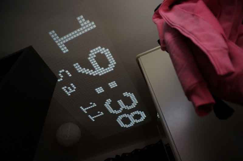
There are plenty of cheap projection clocks available, but as [Thomas Pototschnig] points out in this project, where’s the fun in just buying something? He set out to build a cheap projection clock using a small LCD screen, a cheap LED backlight, and a cheap lens. (Website seems down, try this link courtesy of the Internet Archive if it fails.) Cheap is the order of the day here, and [Thomas] succeeded admirably, creating a design that can be made with a couple of cheap PCBs, a 3D printer and the other parts mentioned above. He does a nice job of laying out his thinking in this design, showing how he calculated the projection path and made other decisions. His project has room to grow as well: it runs from an Arduino compatible STM32 that could handle many things other than showing the time if you were inclined to expand the project further.
[Thomas] has released all of the files he created for the project, including a number of options for the case that can use C-mount and Sony E-mount lenses. I’m not sure if you would want to attach your expensive camera lenses to a home-made projector like this, but it’s good to have the option if you have a dead E-mount lens that you were going to tear apart for parts anyway.


Awesome and well built!
“There are plenty of cheap projection clocks available, but as [Thomas Pototschnig] points out in this project, where’s the fun in just buying something?”
Build one that projects onto a cloudbase.
“His project has room to grow as well”
I usually think if such things as a poor choice of mcu, but you know.. Glass half full and all that.
May have been true somewhere in the ’80-s.
But nowaday’s an STM32 board costs the same as any 8-bitter and getting familiar with ARM probably has more future value than those 8-bitters.
The hard part here is the mechanics, sourcing a compatible LCD with working library, box, uC.
The particular uC used is pretty irrelevant.
Being able to project user defined data is a solid base to expand on with all kind of fun projects.
Addition:
I also see lots of beginners on avrfreaks (for example) who start with a small 8pin tiny AVR and then have to add shift registers or I/O expanders because they run out of pins. A month later the few KB of Ram or Flash they have is filled and they need to switch uC for their project.
This results in a waste of time and frustration, and all for maybe trying to shave EUR 0.50 off of the BOM.
And all the while they do not have extra pins for debugging purposes.
Extra I/O pins for debugging with a Logic Analsyer is an extremely helpfull while searching for software bugs.
An example of what can be done is here:
https://www.avrfreaks.net/forum/led-indicator-software-debugging?skey=debugging%20led
In post #32 there is a clear expanation of how it works, together with a bunch of screenshots from Sigrok / Pulseview.
A hobbyist certainly will not outgrow the STM32F103 family quickly, and small projects like this are perfect for getting familiar with it. It is not a commercial project of which a million units are made. The cost of the uC is irrellevant compared to the rest of the hardware / time.
Hm yea, fair point. My marketing wank detector fired a bit premature! (Guessing had added that remark, but what do you add to a clock that needs a beefy mcu? A 3d printer?)
And yea, the projection is indeed very nicely executed!
A $3 STM32 is the simplest choice for getting USB cheaply :) And you have very good debugging support (using 2 mcu pins) and you can use e.g. Eclipse+CDT als IDE with full debugging (break points, variable inspector …) support :) No reason to use small AVRs anymore :)
Replacing the light source with a de-collimated laser pointer, removing the condenser lens, allows for a lower power and longer range build
Tried that one … dit not work out so great unfortunately. Weird interactions between laser speckles and lcd matrix leads to non-uniformly lit pixels.
This is fantastic – well done! I built something similar a few years back but this is so much better! The image is super crisp! Maybe using a higher resolution display (128×64) displays would be fun?
https://hackaday.com/2015/08/12/cheap-projector-tells-time-invades-space/
is a great project but i don’t get how this is simple or “DIY” as it’s neither simple in time required or complexity. to me it’s almost identical to the prototyping stage of developing a product for market
I take this as a compliment ???? :)
A retired engineer here. Just to let all you young bucks and does know, microchip still sells over 1million 8 bit controllers . Its not a lost commodity.
There are a lot of industrial uses for chips that I wouldn’t even bother with because they’re so small. When you’re ordering hundreds of thousands of units, these things add up. When it’s a one-off hobby project, you can often afford a few extra bucks on a fancier micro.
That said, I hauled out one of my last AVR ATTiny45s just last weekend for a quick-and-dirty.
where can I find the project resources? All the links seem to be dead
We might have slashdotted poor Thomas.
Try the Wayback Machine: https://web.archive.org/web/20241128173803/https://microengineer.eu/2018/05/01/diy-night-clock-projector/