If you are just starting out in electronics, you need tools. But it is hard to build all your tools. Even though we see a lot of soldering station builds, you really ought to have a soldering iron to build the station. It is hard to troubleshoot a multimeter you just built if you don’t have a multimeter. However, a capacitance meter is a handy piece of gear, relatively simple to build, and you should be able to get it working without an existing capacitance meter. [gavinlyonsrepo] presents a simple design using an Arduino, an OLED display, and a few components.
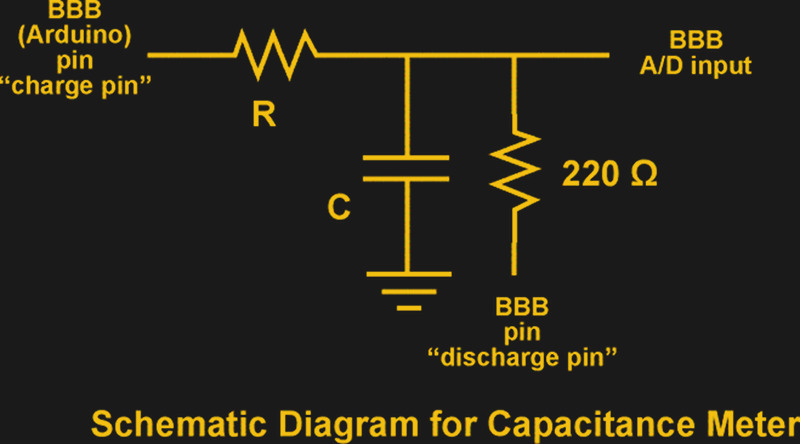
The principle of operation is classic. On one range, the Arduino charges the capacitor through one resistor and discharges it through another while timing the operation. The amount of time taken corresponds to the capacitance.
The other range doesn’t use external components but relies on the internal resistance of the Arduino and the stray capacitance in the chip and the board. Because these parameters vary, you’ll need to calibrate the device with a capacitor of known value.
This is one of those projects that would have been more complicated before microcontrollers. With an Arduino or similar device, though, it is pretty straightforward.
We looked at a project that explores the second method in depth quite some time ago. We’ve seen some similar meters in the past you might enjoy.


https://www.mikrocontroller.net/articles/AVR_Transistortester
$10 delivered, from far east usual suspects.
Every single time with y’all. Missing the point.
untrue and/or unproven. he likely got the point, and he was merely helping me to purchase the item i did not previously know about. thank you to the fella — two of these are on their way! (one for me, one for my cousin.) it’s often unsurprising how the input of others works out.
Ah, that’s what they’re all based on. Useful, thanks
Looks like a fun project, but I wouldn’t suggest anyone even think of buying a multimeter without capacitance measurement unless you’re getting it for a specific task, like how some people prefer analog meters for watching moving signals (I think I’d probably get a DSO nano for that one though).
For that matter, your first DMM should probably have frequency/duty cycle too.
Full featured DMMs are cheap now.
I’d still suggest this project though because measuring capacitance is a useful thing, and you can do a lot with capacitive sensors.
The capacitor will probably at least partly absorb most ESD spikes, and it will also buffer ADC input impedence, so it might also be an interesting way to measure resistance with a bit of extra protection.
Thinking about it more, I’d almost say everyone should get one of those 100 dollar multimeter scope combos, but I don’t have experience with the super cheap ones and standard multimeters are great because of the battery life.
Then again, if you can deal with keeping them charged, and you find one with good reviews it might be worth it.
i picked up one of those free meters from the Harbor Freight depot; the voltages and currents displayed are within 1% of what i’ve expected.
the ($30-50) DSO [kit] scopes aren’t all that great, but just like the free meters, they can be useful and economical. your $100+ scope recommendation is good.
Some of us just have a standard DMM with Volts, Amps and Ohm(and continuety) Keeping an eye out for a local scope though
What are you smoking Daniel?
Personally I am on a hobbyist or lower budget for my electronics tools. I have a Rat Shack multimeter that does capacitance. It’s not the tool a professional would buy but it wasn’t cheap either. I had or have a cheap Chinese one too. (not sure if it’s even still around) The Rat Shack was ok and definitely gave me an ability to check capacitors beyond what I had before I purchased it many years ago. The Chinese one I bought because it did inductance too but it has never been useful to me as much more than a random number generator.
When I worked as a professional our shop had separate meters, big expensive Simpson Volt/Ohm meters and I forget what brand capacitance meter. Those were way better than my Rat Shack multi but also far outside my price range.
Then… something I didn’t foresee happened. Cheap microcontroller based capacitance meters for everyone! My JYE Tech capacitance meter works almost as well as the one I remember from the shop. My no-name AVR-Transistor testor is almost as good of a capacitance meter as the JYE Tech!
I really doubt that the electronics in these super low end meters are actually better than my Rat Shack meter. I suspect that the real difference is the leads. How are you going to do a decent job measuring capacitance through something that plugs in with big old banana jacks? How are you going to measure power circuits with puny connectors that are built for low reactance?
I don’t think mixing all these measurements together into one device is the best way to make a good tool!
This is a good exercise in design and probably a useful tool for testing new capacitors … especially if they came from China.
http://i.imgur.com/PZrQQGI.jpg
Unfortunately it has very limited range due to the fixed resistor values. The old way to measure a large range of capacitance was with a scaled AC variant of a Wheatstone Bridge using a decade box for scale.
This unit is testing based on T=CR where a Wheatstone bridge tests Xc or 1/(2 x Pi x F x C) and can be scaled.
On another note you don’t need so many uC pins as modern uCs have very high input impedance so you can just use a charge and discharge pin and use one as A/D sense alternately when the the other is either charging or discharging.
Most testing of capacitors is for fault diagnostics and a capacitance tester isn’t the ideal tool for this because capacitors have a very high tolerance range and can often test as OK when they are not OK especially if tested when cold.
As capacitors age and are exposed to heat they loose electrolytic properties (especially when hot) while there measured capacitance is often close to normal.
An ESR (Equivalent Series Resistance) meter is a much better meter to test for faulty capacitors.
Its a concept piece more than anything. Its hardly a bench quality device to put a lot of trust in… but there are a lot of us who DO derive joy from making things ourselves from parts we have lying around instead of spending a lot of cash to a quality item or just a spend a little cash for some “made by somebody else and ready to go” glorified “instructable”.
I wouldn’t build or buy a meter like this for a professional repair shop but…
1) Capacitances rarely need to be precise
2) When they do it is usually as part of a tuned circuit. In this case, one side, either the inductor or the capacitor is usually adjustable. Adjustment is made not with a capacitance meter but with a frequency counter, spectrum analyzer or maybe just the technicians ear. In any case it isn’t adjusted to hit a precise capacitance, the circuit is adjusted so that the combination of components hits the correct frequency.
So.. what do most hobbyists need an expensive, precise capacitance checker for anyway?
A cheap tool that gets you in the ballpark is usually enough to identify a poorly marked capacitor or to verify that a capacitor is functional. That and an ESR meter are usually more than enough.
more on point 2… adjusting this way takes into account any stray inductances or capacitances in the circuit as well as any imprecesion in the inductor. Sure, you can calculate a textbook capacitance using the formula but the exact capacitance needed in each device will differ due to all the stray reactances.
Now if we could just modify it to test 500F supercaps without having to wait 10 days for it to charge up.