We just wrapped up the Robotics Module Challenge portion of the Hackaday Prize, and if there’s one thing robots need to do, it’s move. This usually means some sort of motor, but you’ll probably want a gear system on there as well. Gotta have that torque, you know.
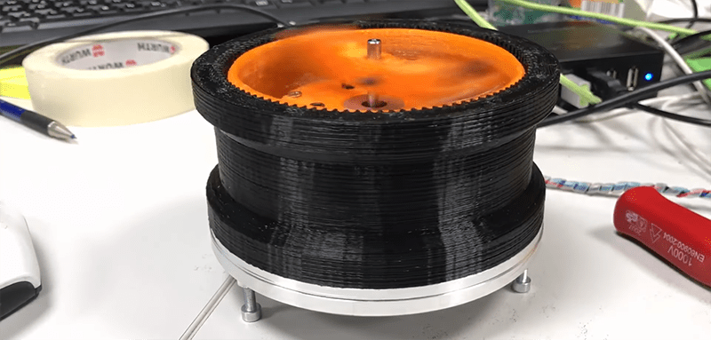
For his Hackaday Prize entry, [Johannes] is building a 3D printed Strain Wave Gear. A strain wave gear has a flexible middle piece that touches an outer gear rack when pushed by an oval central rotor. The difference in the number of teeth on the flexible collar and the outer rack determine the gear ratio.
This gear is almost entirely 3D printed, and the parts don’t need to be made of flexible filament or have weird support structures. It’s printed out of PETG, which [Johannes] says is slippery enough for a harmonic drive, and the NEMA 17 stepper is completely contained within the housing of the gear itself.
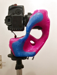
Printing a gear system is all well and good, but what do you do with it? As an experiment, [Johannes] slapped two of these motors together along with a strange, bone-like adapter to create a pan/tilt mount for a camera. Yes, if you don’t look at the weird pink and blue bone for a second, it’s just a DSLR on a tripod with a gimbal. The angular resolution of this setup is 0.03 degrees, so it should be possible to use this setup for astrophotography. Impressive, even if that particular implementation does look a little weird.


We need more weirdly organic hot pink support structures in this world.
can’t guarantee the pink, but as topological optimization becomes more widespread, you’ll get to see a lot more of the organic looking support structures.
SolidEdge ST10 calls it “generative design” and it is impressive.
for what little it’s worth, i think that’s a slightly broader thing. https://en.wikipedia.org/wiki/Topology_optimization vs https://en.wikipedia.org/wiki/Generative_design
According to the link, the shape was “topologically optimized” in Fusion 360. I didn’t know it could do that. I suspect it’s one of the “pay through the nose” features.
At the risk of sounding like SE sales rep (witch I’m not, just to be clear):
SE ST10 free edition has it if you want to try. There is no option to save it as stl but for simple fun is enough.
Why pay through the nose, when you can use Fusion 360 for free (with some limitations to commercial use).
https://www.youtube.com/watch?v=zuUUq0jOVMI explains some basics of how topo-optimiziation works in F360. And there are a lot of other tutorials you can dive in, to get you started…
Are you sure this works on the free license? I’m a heavy Fusion 360 user, and most of the simulation and analysis features are pay-gated. And the generative design features being used here are limited to the super-mega-ultra edition ($1,535 per year).
I just double checked with Autodesk:
“There is no difference in functionality between a Startup subscription type and Fusion 360 Ultimate. In other words, you get all the features in Fusion 360 Ultimate with a Fusion 360 Startup subscription.”
I just looked into it, and while the hobbyist/startup license is indeed for the Ultimate edition, the fancy new generative design tools are only available to paying customers. Apparently, this is because the feature does all its number crunching server-side, and compute time is expensive. Some of the simulation features are in the same boat.
If anyone wants to see some organic looking stuff, You should check out some old Ritter dental equipment.
Look for stuff older than the mid 1970’s
https://picclick.com/Vintage-Ritter-Belt-Driven-Lab-Engine-Dental-Drill-113045784978.html
Not too ugly. Slap a patent on your concept. But make some, bkack and grey, eh? ????
When working in semi conductor automation robotics with these type of gears they are very fragile. Harmonic gears are good at torque until they are not; one “skipped” tooth and they are done(broken). They must be treated like worm gears one side is the input and the other side is the output. But this is a good way to have precision movement (within 10th of a millimeter when put on an arm), and to have a compact reduction gearbox.
Haven’t really experienced much problems with them to be honest (also in the semicon field). But yes, they are not back-driveable and the torque on the output shaft must not exceed the rated limit in any circumstance.
Microstepping the motor would get you down to an angular resolution quite good enough for astrophotography.
…perhaps for very modest definitions of “astrophotography”
As-built, it yields a 1.8 arcminute step size. With a wide angle lens that’s about a pixel, and with microstepping you could make the motion smooth enough so the blur and jiggle is not noticeable, but even microstepping is not going to improve the accuracy more than a factor of 4. Might be OK to track, say, the milky way and capture meteors.
But with anything longer than about a 28 mm lens, the blur introduced by the step size — even with microstepping — yields blurs many pixels in size. Any decent SLR with a good lens (or a small telescope) can resolve better than 10 arcseconds, at least ten times better than this gear ratio can hope to do, even with microstepping. It needs another 60:1 stage for any tracking with a long lens.
Angular resolution = precision. You also want accuracy. Depending on the stepper motor and the stepper controller those micro steps may be considerably “off”. One of the most common stepper motors, the Wantai Motor company 42byghw811, (there are four of them in my Velleman K8200 3d printer) has a step accuracy of 5%. This means that the steps can be off by as much as 5% of 1/200 of a revolution. If you are using 20 or more microsteps, the accuracy of each microstep may be off by as much or more than one of those microsteps. When you are trying to find a star, that accuracy is important.
Remember that microstep are electrical microstep, not mecanical ones. Only 1/2 electrical microstep are really in line with 1/2 mecanical ones, below that torque slip occurs.
This is *begging* for an OpenSCAD script…
You could perhaps extend the SCAD files from Emmett’s implementation: https://www.thingiverse.com/thing:219779