We’re sure all radio amateurs must have encountered the problem faced by [Alexandre Grimberg PY1AHD] frequently enough that they nod their heads sagely. There you are, relaxing in the sun on the lounger next to the crystal-blue pool, and you fancy working a bit of DX. But the sheer horror of it all, a tower, rotator, and HF Yagi would ruin the aesthetic, so what can be done?
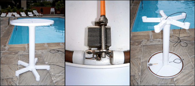
[Alexandre]’s solution is simple and elegant: conceal a circular magnetic loop antenna beneath the rim of a circular plastic poolside table. Construction is the usual copper pipe with a co-axial coupling loop and a large air-gapped variable capacitor, and tuning comes via a long plastic rod that emerges as a discreet knob on the opposite side of the table. It has a 10 MHz to 30 MHz bandwidth, and should provide a decent antenna for such a small space. We can’t help some concern about how easy to access that capacitor is, on these antennas there is induced a surprisingly large RF voltage across its vanes, and anyone unwary enough to sit at the table to enjoy a poolside drink might suffer a nasty RF burn to the knee. Perhaps we’d go for a remotely tuned model instead, for this reason.
[Alexandre] has many unusual loop projects under his belt, as well as producing commercial loops. Most interesting to us on his YouTube feed is this one with a capacitor formed from co-axial soft drink cans.
Thanks [Geekabit] for the tip.


But… polarisation ?
Matters less on HF, the ionosphere will do dirty things to the polarisation anyways.
Horizontal vs. vertical is more about ground gain and takeoff angle on HF.
Now if grt to circular polarisation then you can get advantages.
A bit more gain and much less fading.
But then you get to the fun land of transmitting in RHCP and receiving in LHCP and thus need switching and an antenna where the phasing can be changed.
Since a friend of mine is trying to understand dipoles (we’re all EEs), can you recomend any resources explaining a few of these items with regards to antenna physics?
Unfortunately not really.
There are tons of images on the internet that show the current and voltage distribution on a dipole. The gif’s are also neat.
I find the “dipole is actually a plate capacitor opened up”-explanation to be somewhat intuitive.
But I cannot find the original source on google and I’m not gona draw up gfx at 1:30AM
Asking for a friend.
Antenna Physics: An Introduction
Propagation and Radio Science
Both available from the ARRL store or Amazon. I bought the Kindle versions of each for around $10. Both are good reads. I liked the Propagation and Radio Science better, but if you’re looking specifically for antenna answers, the other would be the better choice. They go well together because you can learn about all the differences in how antennas work, then how the signal actually travels through the atmosphere.
2ftg doesn’t understand YGDES’ question, and the other comments show lack of knowledge on TX loops as well. While there is a lot more material available now than a decade ago, unless you go looking for it and read it, you’ll still be in the dark.
The main thing to remember is that small magnetic loops are MAGNETIC: they radiate in the H (mag) field rather than the E (electric) field (this is not [necessarily?] true for large (1+wavelength) loops). This means things like polarization turn out to be mostly backwards from the way you think of a normal E-field antenna. Yann’s comment is because 99% of the time you want a loop oriented VERTICALLY because it’s essentially an oversized tank circuit: horizontal orientation means that coupling to the ground will be large while it will be minimized when oriented vertically. Most people think this is one of the big secrets of why loops perform better than the math suggests: more energy goes into and gets captured from the air rather than the ground. Noise reduction is a combination of said ground-decoupling and high-Q and VERY narrow bandwidth.
All of this said, when you’re designing for stealth efficiency often goes out the window.
As for the below comments on info, Googling will turn up a ton of info. There are also many books. Just make sure you are looking up small TX loops not mere receive loops.
Good luck! (And I may build this one myself one day!)
Mike N7MSD
Phoenix
P.S. Safety comments below are mostly true: these small mag loops have HUGE reactance values and thus it takes a very small amount of power to create big currents and even bigger voltages! No one should be near the thing when transmitting. (FWIW, from a distance that one picture makes it look a bit like an induction cooker!)
A good idea, but anyone who thinks that horrible utilitarian white plastic furniture looks nice has bigger problems.
Lolz
It doesn’t really need to look nice, given that it’s a pool-side bar table, it actually blends very well with the environment.
I dunno a pool doesnt sound like a bad problem to have
It would be difficult to integrate the antenna in one of this nice metal bar tables :-)
and if you crank the power up, then you can cook your chicken on it :)
Is “cooking your chicken” a euphemism for blasting your maraccas, or poaching your proverbials? ‘cos I think it would be worried about more than a slight RF burn to my knee.
Yeah, nothing suspicious about a cheap plastic poolside table with a coax wire coming out of the bottom. ;)
As I understand things, the electric field close to those type of antennas can be at dangerous levels even with relatively low TX power. You probably wouldn’t want to be sitting at the table whilst transmitting.
Pfft! Who needs to have children? :-p
Do people use Litz wire in loop antenna’s. It would be lighter than copper pipe. But more expensive unless you can scrounge some.
Can use magnet wire also.
Magnet wire has higher resistance because of skin effect. I did some looking around and they do use litz wire in loop antenna’s. I have seen them for crystal radios.
Sure, I’ve only read online and used magnet wire for AM crystal radio. Figure that is a smaller diameter and more turns magnetic loop antenna.
I’ve even read where people used telephone and CAT5 wire since was available.
Interesting also is the ferrite mag loop antennas. I’ve wondered and wanted to use Mu-metal and even Metglas instead to see the difference in performance compared to ferrite. Technically, we can use purified iron, though is heavier. I’m have some projects where I want to test since I have ferrite and lab grade iron powder… though just haven’t gotten around to yet.
Magnet wire is easier to scrounge and find from my experience.
Copper pipe is used to keep the resistance as low as possible. The larger the diameter the better. People have made them using copper foil wrapped around plastic pipe. The larger the diameter the wider the bandwidth.
Litz wire is used for medium wave loop antennas, but only for receiving. It would not handle more than a very few watts, if that much.
More for QRP transmission from what I’ve read.
Avoid intertaining when operating HF, unless you are one of those who can do CW and chat with friends at the same time. N7NET said that.
“on these antennas there is induced a surprisingly large RF voltage across its vanes”
Which is? Or where is it listed? I can’t find it.
It can be a few kV with 20w of transmit power…
A few kV at the antenna terminal? 20 watts at 50 ohms is 32 volts. Is the large voltage because of mismatch?
The high voltage is present across the tuning capacator, not the feed point.
The loop acts as a step up transformer for the RF feed in to it.
The transceiver might see 50ohms or something close to it but the matching circuit will match that 50ohms to whatever impedance the loop is.
And that is something very much not 50ohms.
Resonance amplification. But I did not expect this magnitude. I once had 200Vpp in a 10kHz ferrite transmitter antenna from 12VDC input and 600Vp in a 24V fed series resonant 100kHz circuit (also with ferrite coil) for contactless charging of a small battery
As long as the plastic is substantial enough to hold my all-tube rcvr/xmtr/1500W linear es bug, it would make an exlnt operating/cancer-generating/population control station–W8IMP
So this is a thing now among radio amateurs? This bullshit.
Meanwhile radiation and asbestos is still safe according to the internet crowd right?
Sure… you might have read all the Moscow, Cuban, Uzbekistan, Israel and related denial stories with all the third world seriously mentally ill from degenerate irreversibly brain damaged cocaine cartel countries folks I’m guessing.
For ~$11 you can buy a low power RF cautery tool COTS: https://www.ebay.com/itm/Laser-Age-Spot-Pen-Mole-Warts-Freckle-Tattoo-Scars-Removal-Machine-Useful-US-RF/173077614481
Actually, the RF cautery tool is kind of handy. The larger devices are just mass murderous insane if you’re not valid as most are not using the weapons of mass destruction. Some don’t even realize that poisoning is considered murder in the first degree per in the U.S. 18 USC 1111: https://www.law.cornell.edu/uscode/text/18/1111
Even word definitions are being brain damaged malconstrued. Take for instance the term “Radiological”. Everyone acts like the radiological weapon is only confined to radioactive materials and not radio frequencies. Someone smoked too much crack in more than one way. https://en.wikipedia.org/wiki/Acute_radiation_syndrome
Even non-ionizing radiation can cause ionizing radiation and ionization of gases, liquids and solids. Oh, plasma is what everyone must be thinking in the visible range???? Focused directed energy, pulse train, heterodyne, duty cycles, cavitation… anyone… and sympathetic bioelectromagnetics resonance to cause noise, interference and jamming to death?
Neat stealth antenna and article… though… yeah… I wouldn’t want to sit there.
I see the shipment from Colombia came in alright.
And I didn’t hear about any tariffs either Good for you.
Just because this is a pool-side table, doesn’t mean it has to be used next to a pool. The idea would work quite well in a apartment building whose management is down on visible antennas. What they can’t see, they can’t complain about.
You can eliminate the RF power issues, if you hook the antenna up to a receiver only.
With 20W in the voltage at the capacitor gap is high enough to stay away from it. I know from experience. Also feeding it too much power will most certainly result in arcing between the cap rotor and stator which is not good. So be careful. The bandwidth of 10MHz to 30MHz is large for this type of antenna especially with the capacitor pictured so something is going on there. The real concern though is the height.
At the height pictured the antenna is very much in the antenna’s near field region which will result in inductive coupling to ground and nearby metallic objects and that will rob you of radiating power and mess with the antenna’s Q. If the bandwidth of the antenna without retuning is around 15KHz then your not coupling into the ground, nearby metal objects etc and are ok.
To improve performance make the table leg telescopic and raising the loop will improve this projects performance. Another area to look into improving is using a split stator capacitor. Doing so will eliminate the resistance of the capacitors contact finger which at the cap where the voltage is several KV will add up to a lot of loss. Keep the Q high, and losses low and this will give you a lot of relaxing and fun QSOs.
Nice project, nicely done. Thanks for sharing.
A lot of mess in the original text and in comments. A mag loop antenna is in nature very narrow bandwidth antennas, just a few tenth of kHz. But the small size may certanly give a frequency range of 20 to 30 MHz.
A horizontal mounted mag loop antenna just radiate vertically up in the sky. And there is more or less no conern either on power. The shown capacitor can hardly stand for more than 1500 V, which means about 10 watts of power before arcing starts.
Goran
OH1AWE