Although it dates back to the early days of the Marconi Company in the 1920s, the Franklin oscillator has remained a relatively obscure circuit, its memory mostly kept alive by ham radio operators who prize its high stability at higher frequencies. At the core of the circuit is an LC tank circuit, a fact which [nobcha] used to build quite a precise LC meter.
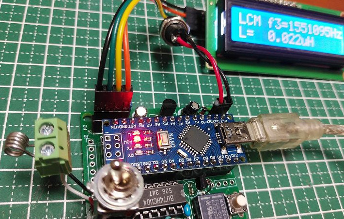 The meter is built around two parts: the Franklin oscillator, which resonates at a frequency defined by its inductance and capacitance, and an Arduino which counts the frequency of the signal. In operation, the Arduino measures the frequency of the original LC circuit, then measures again after another element (capacitor or inductor) has been added to the circuit. By measuring how much the resonant frequency changes, it’s possible to determine the value of the new element.
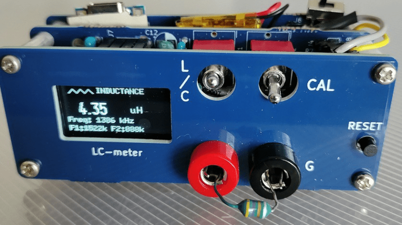
Before operation, the meter must be calibrated with a known reference capacitor to determine the values of the base LC circuit. In one iteration of the design, this was done automatically using a relay, while in a later version a manual switch connects the reference capacitor. Because the meter measures frequency differences and not absolute values, it minimizes parasitic effects. In testing, it was capable of measuring inductances as low as 0.1 µH.
We’ve seen a few homebrew LC meters here, some battery-powered and some rather professional.


Without compensating for inductance of this resistors leads those measurements are about as accurate as throwing pineapples at bats. Even if you do its gonna end covered in guano.
First hint might be that resistor is, in fact, an inductor.
Why would anyone throw pineapples at baseball bats???
Probably to make the life of the guy catching the balls ( pineapples, in this case ) more difficult.
You throw pineapples at cricket bats. The crickets then feed on the pineapples. Obvs.
“First hint might be that resistor is, in fact, an inductor.” I’d just like to point out that even I could see that from the photo and I can say without fear of contradiction that I really know very little, hence my name. Learned it from this site in fact.
From the referenced article:
His example is measuring 10 mH with what appears to be 4″ leads. That’s about 100 nH for two leads (200 nH total), which is about 1/50,000 of the value he’s measuring.
I’m willing to believe your comment, but can you could elaborate a little? How will the inductance of the leads cause so much problems?
Thank you for your insightful comment. You’ve pointed out a weakness in this measurement method. However, the inductance of the lead wire is generally around 10-something nH. Therefore, for air-core coils with 10 or more turns (0.1 μH or higher), the measured value should be a reasonable estimate.
If anyone is interested in making inductors with a high Q value, I’ve got a project to help with that.
Making a coil with a specified inductance is easy and straightforward using the standard formula, but you won’t know how good it will be in the circuit. Many combinations of diameter, length, and wire thickness will arrive at the same inductance when built, and some of these will have a high Q value and some will not.
And some coils that measure out to a specific inductance will act like capacitors when used at RF frequencies! (From inter-winding capacitance, which grows larger with higher frequencies.)
My project has programs that will scan through the parameters and generate a table of characteristics for each parameter set, allowing the user to select the best configuration that meets their needs.
For example, you can choose the configuration that gives the highest Q-value, or highest self-resonant frequency, or lowest material cost, and so on.
https://hackaday.io/project/193000-inductance-design-tools
From inter-winding capacitance, which grows larger with higher frequencies.
Really? Interesting. Is this some kind of skin effect thing?
I meant reactance; or alternately, could have said “the effect of which” grows larger with higher frequencies.