Infrared certainly has its uses, but if you’re trying to locate objects, ultrasonic detection is far superior. It’s contact-less, undetectable to the human ear, and it isn’t affected by smoke, dust, ambient light, or Silly String.
If you have one ultrasonic sensor and a microcontroller, you can detect plenty of useful things, like the water level in a rain barrel or the distance traveled by a tablet along a rail. If you have two sensors and a microcontroller, you can pinpoint any object within a defined range using trigonometry.
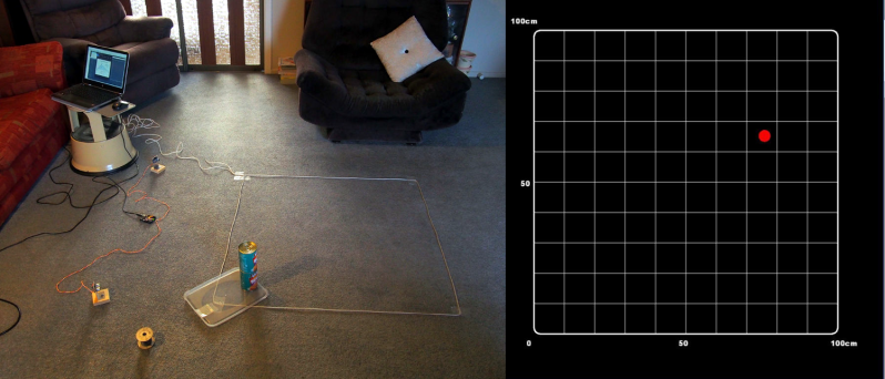
[lingib]’s dual sensor echo locator uses two HY-SRF05s, but the cheap and plentiful HC-SR04s will work, too. Both sensors are arranged for maximum beam overlap and wired up to an Arduino Uno. One sensor’s emitter is blocked with masking tape, so all it does is listen.
When the system registers the object, it shows up as a red dot on a grid inside a Processing sketch along with a bunch of details like the object’s coordinates, its distance from each sensor, and the area of the triangle formed by the two sensors and the object. [lingib] reports that the system is quite accurate and will work for much larger playgrounds than the 1 meter square in the demo after the break.
Don’t want to detect objects? Ultrasonic sensors are cheap enough to hack into other things, like this one-way data communications module.
Thanks for the tip, [Setvir].


Do you really need trig? The object is on the intersection of two arcs. It sounds like a compass and straight edge problem, which makes it Euclidean Geometry.
how do you code that?
I think you get the algebraic equations for two circles and solve for the intersection(s). The sensors produce a radius and the setup gives the separation of the sensors. When there are two solutions, use absolute value and pick the direction you want. I’ll try to do an algorithm if I have the time. I think it is rather simple in the end and could use rational arithmetic and no floating point.
Draw a line between the sensors and call it the x-axis. Do everything in this “sensor space” with units in terms of sound travel time. Transform to real coordinates later. The sensors return a radius in sensor units. The two circles will intersect and a lone drawn between the two intersection points will always be perpendicular to and centered on the x-axis. The half-length of this line is the y coordinate of the target and the lines position on the x-axis is the x coordinate. This is pretty basic x squared plus y squared = r squared and y=mx+b stuff and reduces to some addition, multiplication, and maybe a square root. No trig. The transformation to coordinates that set scale, and maybe a rotation and translation use constants that are calculated once. (Scale, translate, reflect, and rotate are done in the same operation – in the US, first or second year high school math).
Here ya go. http://s1091.photobucket.com/user/Comedicles/media/Sonar_zpslh2a4rcl.jpg.html
I’ll use the labels of the author. The base line between sensors is found either by measuring or using the sensor to calibrate. The sensors at A and B, determine a and b, the radius from each to the target. Some fiddling and substituting with the equations for circles (x^2 + y^2 = r^2) gives the equation in the box. Oops. R^2 should be b^2.
Computationally you can save a little by working in a scaled system with c=1.
However, there is a way to do this nearly instantly. Given you can get very tiny EEPROMs for under $1 US that have huge capacity, one should put them on everything. In this case you can pre-compute a lookup table so that the raw integers from the sensors can be used as an address and the contents of that address are the coordinates of a target at that location. For example, a resolution of 1000 by 1000 grid is one million points. That can be millimeters in a one meter square or whatever you want. You need x and y for each place, so that is probably 32 bits and you address the EEPROM in 4 byte chunks.
So, get data from sensor, use as address (or shift left 2 bits first – which is free in an ARM), read EEPROM, done. Any scaling can be worked into the data.
It seems to me that it would be a bit simpler mathematically to use 2D triangulation, no? Of course you would have to alternate the emission of the two ultrasounds emitters so they don mix up, but this delay would be very small and would not impact the result by much.
Silly question, but since this is inside the frequency range of cats and dogs, will prolonged cause permanent damage ?
https://en.wikipedia.org/wiki/Hearing_range
The HC-SR04’s that I’ve quickly measured using an Airspy+Spyverter+electret microphone are pretty much bang on 40kHz (there was some additional RF signal leaking in through the power supply cables that were providing power to the electret microphone, that is what the signals to the right are).
(3v DC to power electret microphone)
https://i.imgur.com/yZ0fffq.png
(12v DC to power electret microphone)
https://i.imgur.com/ftZE7If.png
(silly circuit)
https://i.imgur.com/z1QZTW6.png
I should probably add that I turned up the external power supply slowly from zero volts to 12 volts, 0.1 volt at a time to avoid any chance of a massive +35dBm and destroying my RF hardware. Initially I had a 40dB attenuator at the RF input but removed that once I saw the signal levels involved.
“high accuracy” in the title is quite questionable. I see 10-15 cm jumps of the red dot on the screen. The title of this article is then relatively inaccurate.
Did you notice that the object to be tracked was moving ?
This should explain some of the jumps you mentioned.
Does this only work for having one object in the field of vision at a given time? Like, could you confuse it by placing two items such that the receiver gets multiple ping responses and things so it thinks the distance is jittering? If, so, would it be feasible to possibly account for any arbitrary number of objects in the field of view?
The HY-SRF05 is not overly complex, so it will only return the range to the first object it finds, everything further away would not be measured.
http://www.hmangas.com/Electronica/Datasheets/Sensores/HY-SRF05/
U1 is going to be a 4 MHz, 12 I/O pin, 8-bit Microcontroller (probably a cheap Microchip PIC with 25 bytes of RAM and 512 to 1024 bytes of flash).
U2 is going to be a 3-V to 5.5-V RS-232 Line Driver, with ±15-kV ESD Protection, an ST202 or a MAX3232
U3 is a Quad Low-Noise JFET-Input General-Purpose Operational Amplifier
The MCU to do all the timing and and control, the RS-232 Line Driver chip to zap the TX with 12 to 30 volts to make it vibrate loudly, and 4 amplifiers to bring the signal level of the returned signal (RX) high enough to be detected and processed by the MCU.
I was close with the MCU, they are actually clones of PIC’s with 13-bit instruction set:
https://en.wikipedia.org/wiki/List_of_common_microcontrollers#ELAN_Microelectronics_Corp.
With only two sensors there are an infinite number of points that are possible locations for the object.
The object is at the intersection of two circles in a plane. One on either side of the line connecting the sensors. That is, two points, and one is easily rejected. In space it lies on a circle formed by the intersection of two spheres. With three sensors in 3D it is the intersection of a circle and a sphere, which is a point determined by the physical constraints.
That is IF they are in the plane.
It is always in a plane defined by the object, and two sensors.
Each sensor returns a distance to the object. Geometrically the set of points having the same fixed distance to each sensor is a circle with its center at the midpoint of a line between the two sensors and lying in a plane perpendicular to the line between the sensors. Two sensors cannot resolve to single point in 3d space.
I’m making the simplification that his floor is a 2D surface used as the reference for position. If the target is constrained to be on the floor, there is no 3rd dimension in the problem.
I don’t follow this “Geometrically the set of points having the same fixed distance to each sensor is a circle with its center at the midpoint of a line between the two sensors and lying in a plane perpendicular to the line between the sensors. “.