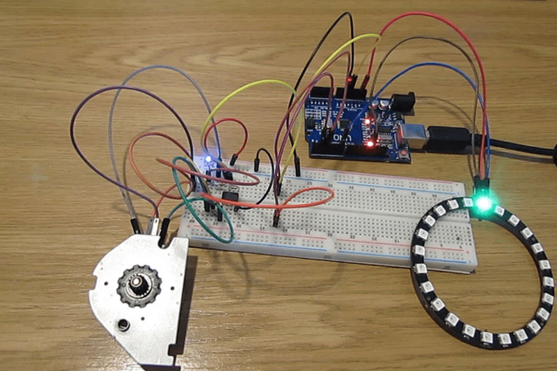
We always think it is interesting that a regular DC motor and a generator are about the same thing. Sure, each is optimized for its purpose, but inefficiencies aside, you can use electricity to rotate a shaft or use a rotating shaft to generate electricity. [Andriyf1] has a slightly different trick. He shows how to use a stepper motor as an encoder. You can see a video of the setup below.
It makes sense. If the coils in the stepper can move the shaft, then moving the shaft should induce a current in the coils. He does note that at slow speeds you can miss pulses, however. Again, the device isn’t really optimized for this type of operation.
The circuit uses an opamp-based differential amplifier to read the pulses from the coil. Two opamps on two coils produce a quadrature signal just like a normal encoder. When the shaft turns in one direction, one pulse will lead the other. In the other direction, the lead pulse will be reversed.
There’s code to let an Arduino read the pulses. And here’s plenty of code that will read quadrature on an Arduino or other processors. We’ve seen similar hacks done with hard drive motors which are quite similar, by the way.


As for second part of video, here someone make it with even simpler method ;)
https://youtu.be/c2tBwzq4G18?t=10
That one doesn’t work so well at low speed.
Here’s a similar project but with pcb gerbers available.
http://www.webx.dk/oz2cpu/20m/encoder.htm
@Al Williams, I was suitably outraged by the alleged Patreon paywall. But then I read the Instructable, and the example code appears to be freely available as linked from the page. The Patreon link is just an invitation to support the author’s work. Either I’m missing something, or you may be doing the author a disservice–can you please double-check?
I wish we could up vote comments.
+1
C’mon, it’s a good thing that not everything is Reddit.
@Al Williams, thanks for the correction.
The ETC “MicroVision” lighting control console used a stepper for an encoder and it had a wonderful “feel” to it with the magnetic detents.
I was remembering the same thing on the ETC Impression…I was just going to go down and pop the lid on one of the ones we have in storage and see if I was remembering correctly.
So you could move your mechanism in an arbitrary path while recording, then replay the path. Cool!
Hard disk spindle motors can be two phase stepper motors, or three phase BLDC motors, mostly on more recent drives I think.
I’ve always found the “this pulse leads the other” confusing; both channels have long series of pulses, all indistinguishable from each other. How can you say one channel leads the other?
If you state instead that the first channel is low on the rising edge of the second channel for one direction, and high for the other, it makes perfect sense. From there, is not hard to see how the direction would be determined, why an encoder doesn’t lose track of the position when it’s moving back and forth on an edge, and how this can be extended to count all four edges for maximum resolution.
The circuit in this article uses the forward voltage of a (Blue) LED as a reference voltage. LEDs make a lot of noise so that may be why it skips steps when turned slowly.
I saw another circuit in the comments here and it was better at dealing with the back EMF but it had no hysteresis.
Here are another who examples, each only one channel of the two needed.
https://cdn.hackaday.io/images/7088311531693504394.png
Both use the ratio of R4/R5 (R9/R10) to set the hysteresis to 1/100 or 0.05 Volts. The hysteresis needs to be higher than the noise level. and that ratio ban be adjusted.
The other differences are how the diodes are arranged. In both cases they will limit the input to the op-amp to 2.5 Volts +/- 0.6 Volts.
In both cases the PIV (Peek Inverse Voltage) is protected bu the Vf (Forward Voltage) of the other diode so you don’t need to worry about PIV.
In the top circuit most of the back EMF is absorbed by the 100k resistor R3 so D1 and D2 can be small signal diodes like a 1N4148,
In the bottom circuit the diodes (D3, D4)shunt all the current from the back EMF so perhaps they should be something like 1N4001 or the more common 1N4004.
Because the back EMF is shunted in this way in the bottom circuit, turning the stepper will feel more notched and that may be desired feature.
Hi RÖB. Which software did you use to draw these schematics? They look nice.
I used an online drawing tool at
https://www.digikey.com/schemeit/project/
or
https://www.digikey.com/schemeit/
It’s the first time I have used it so it’s obviously easy to use.
Looks a lot like geda-gschem which I’ve used for the last 20 years. http://www.geda-project.org/
Here’s a stepper used as an encoder with force-feedback:
https://www.mikrocontroller.net/topic/341165
This is another use of a stepper to provide mechanical feedback for a Jog/Shuttle knob in a video editing set-up from 1989/90. https://photos.app.goo.gl/RBLTAW8LeL1DDjvr7 There is quite a long description to go with the photo, but basically the custom keyboard with the coloured keys has the editing controls. The Jog/Shuttle knob has an optical shaft encoder for position data, and a stepper motor to provide mechanical feedback. In Jog mode the knob could spin continuously, and the stepper provided both a “cogging” effect for slow speed feel, and a brake to stop it when you let go. Pressing the knob or one of the buttons above it would switch to Shuttle mode, and the stepper would then provide end stops and a return to centre “spring” effect. The action was the best I have ever used, but it cost me an additional £750 on top of the £15K for the computer, the editing software, the VTR interfaces and a video preview switcher.
Great Scott tried something similar last year with a 3 phase motor: https://www.youtube.com/watch?v=tjCJ3MlFt7g It had the same downsides.
That gave me an idea back then. What if you drive one phase with a small AC signal (square wave from a MCU) and check for the EM coupling on the other two? Basically the motor is used as a low res. inductive encoder. If you turn the rotor, the “output” signals will be asimmetric. I tried it once, and it was indeed significant, measurable with an oscilloscope. But I didn’t have the patience to go any further since then.
You could have an encoder which works at single steps and has a nice tunable haptic feedback.
Hack it! Shameless selfbump.
https://hackaday.io/project/160585-motor-as-encoder
Why are you leaving your private ads here? It has no relevance to this.
Nice work! Angle sensing from BLDC motor like HDD spindle motor