It’s a story we’ve told dozens of times already. The cost to manufacture a handful of circuit boards has fallen drastically over the last decade and a half, which has allowed some interesting experiments on what PCBs can do. We’ve seen this with artistic PCBs, we’ve seen it with enclosures built out of PCBs, and this year we’re seeing a few experiments that are putting coils and inductors on PCBs.
 At the forefront of these experiments in PCB coil design is [bobricious], and already he’s made brushless and linear motors using only tiny copper traces on top of fiberglass. Now he’s experimenting with inductors. His latest entry to the Hackaday Prize is a Joule Thief, a simple circuit, but one that requires an inductor to work. If you want an example of what can be done with spirals of copper on a PCB, look no further than this project.
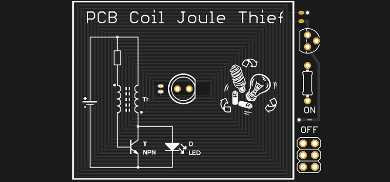
The idea was simply to make a Joule Thief circuit. The circuit is not complicated — you only need a transistor, resistor, and an inductor or transformer to boost the voltage from a dead battery enough to light up an LED.
The trick here is that instead of some wire wrapped around a ferrite or an off-the-shelf inductor, [bobricious] is using 29 turns of copper with six mil traces and spacing on a PCB. Any board house can do this, which means yes, you can technically reduce the BOM cost of a Joule Thief circuit at the expense of board space. This is the year of PCB inductors, what else should be be doing with creative PCB trace designs?


Dumb question – could you make a 3 layer board with some kind of ferrite material for the middle layer and the use vias to “coil” the traces around the outer 2 layers and thereby reduce the foot print?
Or just stack layers of coils on top of each other in the layers of the PCB?
I’ve seen this done, actually, as well as adding some flat ferrite to the outside. You still don’t get super good density, but it can still be cheaper than winding and mounting a core. Think of a ferrite made like a fridge magnet with scotch tape adhesive on one side and you’re about there.
The technique is usually used at fairly high frequencies where it doesn’t cost so much space…
The ferrite (or iron, or powdered iron) has to go THROUGH the coil, or it does nothing. How much iron to put there (in cross-sectional area) is a tradeoff between the area it takes (taking away from the area available for copper and the increased flux density you get from having a core. In commercial devices that use a PCB coil and powdered iron core, the core is usually two pieces, one of which is either E or C shaped, the other either the same or just flat. Only one end of the C, or the middle of the E goes through the coil, the other ends goe around the outside of the coil. It’s just like a discrete transformer or iron-core inductor, but with the windings done as PCB traces instead of insulated wire.
If that was true there wouldn’t be any ferrite backing on wireless charging coils. It needs to be in the magnetic field, so that it can participate, but it doesn’t need to be “through” the coil.
It doesn’t have to go through. If you want more inductance it’s better to have it on both sides, but having it on one side is fine as well. Think of what the fields do. It’s like the difference between a microstrip and stripline transmission line; air-and-fr4 vs fr4-and-fr4.
You can use a ferrite core that goes through holes in the PCB, which is called a planar transformer or inductor. I designed a DC/DC converter a few years back that used such a transformer, which results is very good coupling, very low leakage inductance, and a flat design.
On the other hand, you could use a thicker PCB, with a small torroid core in a milled-out section in the middle, with traces and via through the whole stack as windings. The Murata NXE1 DC/DC converter uses this technique, google that for a picture.
Check out the Murata NXJ1 series of DC-DC converters – it’s a really thick PCB with a ferrite core in the middle (inserted before the top lamination is applied), with traces and vias to make the windings. Very cool. I’m amazed they sell for only $3.50 in single quantities.
How does the cost of the larger PCB compare to the cost of a discrete inductor? PCB area isn’t (usually) free.
Inductors and transformers are among the most expensive components, but yes, that has to be considered on a case-by-case basis.
Most cheap PCB manufacturers offer a fixed price on any board under 10cm x 10cm (4 inch x 4 inch).
Keep your board under that limit, and the inductor is effectively “free”.
If you put a schottky in series with the LED, you can go up to significantly high frequencies making the needed coil a lot smaller
This, +++
48V Telco quarter brick power supplies are made with pcb inductors (on 12-20+ layers) at least a decade.
*With planar pcb transformers.
I think I first used one about 15 years ago.
Flip Dots are manufactured by some makers with PCB coils.
Unlike more classical wound coils, they have a lower operating voltage and (in return) a higher operating current.
But they are lighter and cheaper.
Is the inductance of a ‘space filling’ curve like a Moore curve (https://en.wikipedia.org/wiki/Moore_curve ) somehow notably less (perhaps even ~0.0)? Because the advantage there is the two leads come out next to each other on the same side of the board.
(dammit) s/notably less/notably less inductive/
That would make for a rather complex magnetic field. I suspect it would not be very useful in this application, due to interfering fields. Normally you would want the field from each turn of the coil to add to the previous one.
Inductance of a coil is proportionate to the square of the net number of traces going in the same direction. So regardless of whether it’s a proper space-filling curve or just boustrophedon, any given bit of inductance will be undone by another one going the opposite direction.
If you look at any low-cost electronic product, e.g. a mouse or wall charger or toy, they don’t make inductors and transformers from PCB coils. The small power ratings that you can achieve with such structures can be made with tiny, inexpensive components, and the resulting board area is small, so they fit into small packages.
It’s an interesting idea, and it’s useful for educational or “gee whiz” purposes, but not so much a practical thing that we will be seeing in real products.
It may not be practical, but it is practicable, and since there is some effort to hype it it is safe to say that we will be seeing it in real products! :)
A lot of people don’t realize how cheap the small unshielded inductors are. I’ve even got a bag of through-hole ones I paid a couple cents each for. I’d expect people making things that aren’t going to receive extensive testing to spend a bunch of time designing in these PCB inductors without even having even glanced at the mouser listing for all stocked inductors with the sorting set to price.
My experience with cheap inductors for DIY projects is that I’m more interested in saving money when ordering parts, but then when I build something I don’t actually mind spending $1 on a nice inductor. I’ve got too many cheap inductors in the parts bin to fantasize about the PCB coils :)
It depends on the power and frequency. You see etched inductors very commonly in RF circuits. All matter of receivers and higher frequency transmitters where the skin effect starts to come into play and most of the current in the inductor can flow through the gold plating. Inductors etched on PCB’s are definitely not just a lab curiosity.
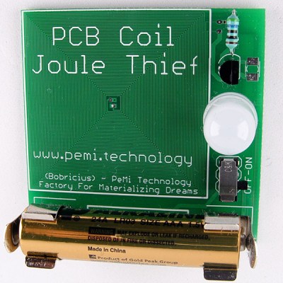
Please correct me if I am wrong, but isn’t that an inductor shown in the photo just above the transistor? I have made hundreds of Joule Thief circuits including some that can light hundreds of leds from a single AA battery and I have also used inductors like that green one in the photo. Similar ones are used in the circuits that power the garden solar lights which is where I got some of mine. Is he using both the wire wound one on the pcb and the other one shown? This confuses me.
It’s a high tolerance resistor. Not really required in this application, but maybe that’s what he had on hand with the proper value.
Thanks Brian. I have several inductors that look exactly like that. Also, I am easily confused, ha ha.
in this case it appears to be a resistor to lower the current to the base of the transistor.
Yes, all of my J.T.s used resistors, some of them used variable resistors. I guess I have never seen a high tolerance resistor and, the inductors I have look a lot like them. Thanks.
I think that’s a 560 ohm 1% resistor which limits the transistor base current. Resistor-like axial inductors usually have a brighter green body.
https://youtu.be/kgYtYXVkan0
I remember having seen PC-trace inductors in various radio kit ever since the late 1970s, so I’m not sure if there really is “a year for them” as such. Though these usually are a few turns operating at VHF, wiith corresponding small inductance. They tend to have larger interwinding capacitance and lower Q than many other inductor designs, which is something that will need to be considered. Still there is this neat thing about these, that they are made “built-in” to the card, and when large area is no problem, or even desirable, using them makes sense.
Would this be a good jumping point to learn about stripline, and microstrip?
You have a circuit that works down in the kHz range. I’ve seen articles where a commercial FM antenna is built on PCB. While I suspect microstrip etc. are more effective above 400MHz, it would be interesting [and educational] to see a mix of conventional and stripline design around 140MHz .
Why not just use a mounting screw as your inductor? Not peripherally located, i know, but still.
Don’t forget Megavolt.nl’s PCB Tesla coil.