Line Following Robot Without The Lines

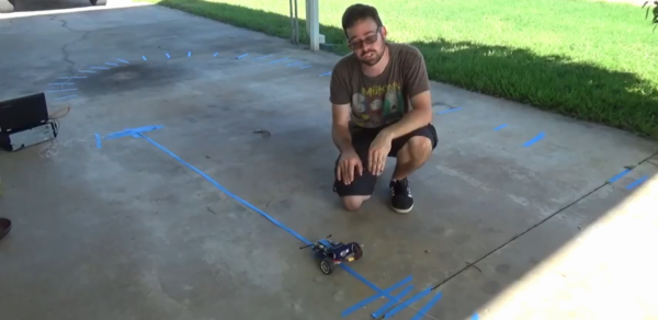
Line-following robots are a great intro to robotics in general, since the materials and skills needed to build a good one aren’t too advanced. It turns out that line-following robots are more than just a learning tool, too. They’re pretty useful in industry, but most of them don’t follow visible marked lines. Some, like this inductive guided robot from [Randall] make use of wires to determine their paths.

Some of the benefits of inductive guidance over physical lines are that the wires can be hidden in floors, so if something like an automated forklift is using them at a warehouse there will be less trip hazard and less maintenance of the guides. They also support multiple paths, so no complicated track switching has to take place. [Randall]’s robot is a small demonstration of a larger system he built as a technician for an autonomous guided vehicle system. His video goes into the details of how they work, more of their advantages and disadvantages, and a few other things.

While inductive guided robots have been used for decades now, they’re starting to be replaced by robots with local positioning systems and computer vision. We’ve recently seen robots that are built to utilize these forms of navigation as well.

Continue reading “Line Following Robot Without The Lines”

Scanning Tunneling Microscope Packs The Bits

We don’t usually think of a microscope as an active instrument, but researchers in Canada have used a scanning tunneling microscope to remove or replace single hydrogen atoms from the surface of a hydrogen-passivated silicon wafer. If the scientific paper is too much to wade through, there’s an IEEE Spectrum article and a video that might run on the 6 o’clock news below.

As usual with these research projects, there is good news and there is bad news. The good news is that — in theory — a memory device made using hydrogen lithography could store 138 terabytes per square inch. That’s enough, apparently, to store the entire iTunes catalog on a quarter. The bad news? Well, right now this takes exotic lab equipment at very low temperatures and pressures.

Continue reading “Scanning Tunneling Microscope Packs The Bits”

IBM PCjr Revived By An ATX Power Supply And Many False Starts

The IBM PCjr was a computer only the marketing geniuses of a multi-billion dollar corporation could love. On the face of it, it seemed like a great idea – a machine for the home market, meant to complement the “big boy” IBM PC in the office and compete against the likes of Apple and Commodore. What it ended up as was a universally hated, only partially PC-compatible machine which sold a mere half-million units before being mercifully killed off.

That doesn’t mean retrocomputing fans don’t still snap up the remaining machines, of course. [AkBKukU] scored a PCjr from a thrift store, but without the original external brick power supply. An eBay replacement for the 18-VAC supply would have cost more than the computer, so [AkBKukU] adapted a standard ATX power supply to run the PCjr. It looked as if it would be an easy job, since the external brick plugs into a power supply card inside the case which slots into the motherboard with a card-edge connector. Just etch up a PCB, solder on an ATX Molex connector, and plug it in, right? Well, not quite. The comedy of errors that ensued, from the backward PCB to the mysteriously conductive flux, nearly landed this one in the “Fail of the Week” bin. But [AkBKukU] soldiered on, and his hand-scratched adapter eventually prevailed; the video below tells the whole sordid tale, which thankfully ended with the sound of the machine booting from the 5-1/4″-floppy drive.

In the end, we’ve got to applaud [AkBKukU] for taking on the care and feeding of a machine so unloved as to be mentioned only a handful of times even on these pages. One of those articles marks the 25th anniversary of the PCjr, and lays out some of the reasons for its rapid disappearance from the market.

Continue reading “IBM PCjr Revived By An ATX Power Supply And Many False Starts”

Ease Rover Development With These Self-Contained Track Units

Tracked drive systems are great, but implementation isn’t always easy. That’s what [nahueltaibo] found every time he tried to use open sourced track designs for his own rovers. The problem is that a tracked drive system is normally closely integrated with a vehicle’s chassis, mixing and matching between designs is impractical because the tracks and treads aren’t easily separated from the rest of the vehicle.

To solve this, [nahueltaibo] designed a modular, 3D printable rover track system. It contains both a motor driver and a common DC gearmotor in order to make a standalone unit that can be more easily integrated into other designs. These self-contained rover tracks don’t even have a particular “inside” or “outside”; they can be mounted on a vehicle’s left or right without any need to mirror the design. The original CAD design is shared from Fusion 360, but can also be downloaded from Thingiverse. A bit more detail is available from [nahueltaibo]’s blog, where he urges anyone who tries the design or finds it useful to share a photo or two.

3D printed tank tracks — including this one — often use a piece of filament as a hinge between track segments and sometimes slightly melted on the ends to act as a kind of rivet, which is itself a pretty good hack.

This Is The Year Of PCB Inductors

It’s a story we’ve told dozens of times already. The cost to manufacture a handful of circuit boards has fallen drastically over the last decade and a half, which has allowed some interesting experiments on what PCBs can do. We’ve seen this with artistic PCBs, we’ve seen it with enclosures built out of PCBs, and this year we’re seeing a few experiments that are putting coils and inductors on PCBs.

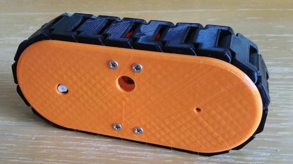
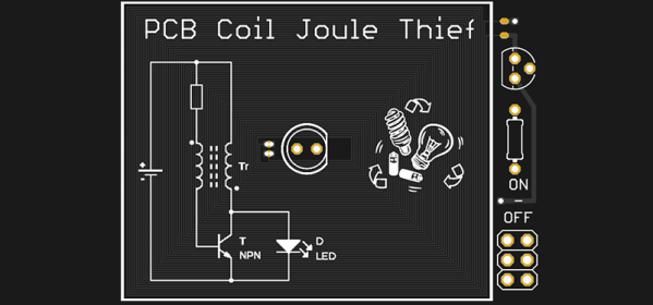
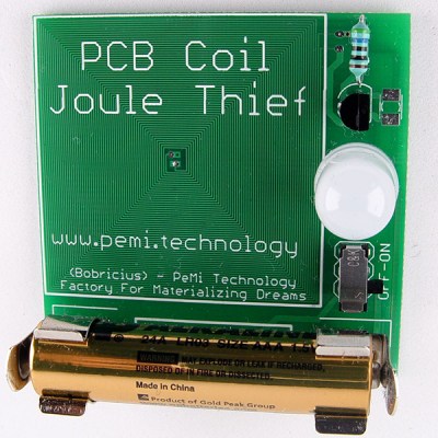
At the forefront of these experiments in PCB coil design is [bobricious], and already he’s made brushless and linear motors using only tiny copper traces on top of fiberglass. Now he’s experimenting with inductors. His latest entry to the Hackaday Prize is a Joule Thief, a simple circuit, but one that requires an inductor to work. If you want an example of what can be done with spirals of copper on a PCB, look no further than this project.

The idea was simply to make a Joule Thief circuit. The circuit is not complicated — you only need a transistor, resistor, and an inductor or transformer to boost the voltage from a dead battery enough to light up an LED.

The trick here is that instead of some wire wrapped around a ferrite or an off-the-shelf inductor, [bobricious] is using 29 turns of copper with six mil traces and spacing on a PCB. Any board house can do this, which means yes, you can technically reduce the BOM cost of a Joule Thief circuit at the expense of board space. This is the year of PCB inductors, what else should be be doing with creative PCB trace designs?

Circuit VR: Starting An Amplifier Design

Sometimes I wish FETs had become practical before bipolar transistors. A FET is a lot more like a tube and amplifies voltages. Bipolar transistors amplify current and that makes them a bit harder to use. Recently, [Jenny List] did a series on transistor amplifiers including the topic of this Circuit VR, the common emitter amplifier. [Jenny] talked about biasing. I’ll start with biasing too, but in the next installment, I want to talk about how to use capacitors in this design and how to blend two amplifiers together and why you’d want to do that.

But before you can dive into capacitors and cascades, we need a good feel for how to get the transistor biased to start with. As always, there’s good news and bad news. The bad news it that transistors vary quite a bit from device to device. The good news is that we’ll use some design tricks to keep that from being a problem and that will also give us a pretty wide tolerance on component values. The resulting amplifier won’t necessarily be precise, but it will be fine for most uses. As usual, you can find all the design files on GitHub, and we’ll be using the LT Spice simulator.

Continue reading “Circuit VR: Starting An Amplifier Design”

OTTO: A Pi Based Open Source Music Production Box

Want an open source portable synth workstation that won’t break the bank? Check out OTTO. [Topisani] started OTTO as a clone of the well-known Teenage Engineering OP-1. However, soon [Topisani] decided to branch away from simply cloning the OP-1 — instead, they’re taking a lot of inspiration from it in terms of form factor, but the UI will eventually be quite different.

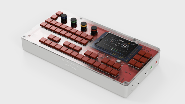
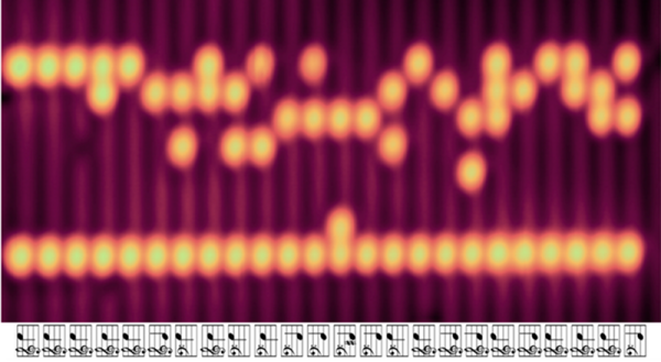
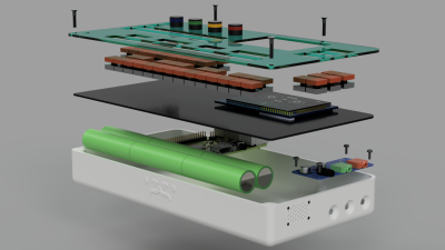
On the hardware side, the heart of the OTTO is a Raspberry Pi 3. The all-important audio interface is a Fe-Pi Audio Z V2, though a USB interface can be used. The 48 switches and four rotary encoders are wrangled by a pair of Arduino pro micros which pass the data on to the Pi. Data is related to the user through a 320×200 LCD.

The software is being written from scratch in C++17. If you’re not a hardcore C++ developer, don’t worry. The synth engines, audio effects, and other DSP software is written in Faust, which is a bit easier to learn.

OTTO is actively being developed, with synth engines already running, a prototype in progress, and fleshed out guidelines for programming the UI. If you’re into creating music, this one is worth checking out, as is Zynthian, another Raspberry Pi based synth.