If you are in any way connected with radio, you will have encountered the low pass filter as a means to remove unwanted harmonics from the output of your transmitters. It’s a network of capacitors and inductors usually referred to as a pi-network after the rough resemblance of the schematic to a capital Greek letter Pi, and getting them right has traditionally been something of a Black Art. There are tables and formulae, but even after impressive feats of calculation the result can often not match the expectation.
Happily as with so many other fields, in recent decades the advent of affordable high-power computing has brought with it the ability to take the hard work out of filter design, Simply tell some software what the characteristics of your desired filter are, and it will do the rest. The results are good, and anyone can become a filter designer, but as is so often the case there remains a snag. The software calculates ideal inductances and capacitances for the desired cut-off and impedance, and in selecting the closest preferred values we modify the characteristics of the result and possibly even ruin our final filter. So it’s worth taking a look at the process here, and examining the effect of tweaking component values in this way.
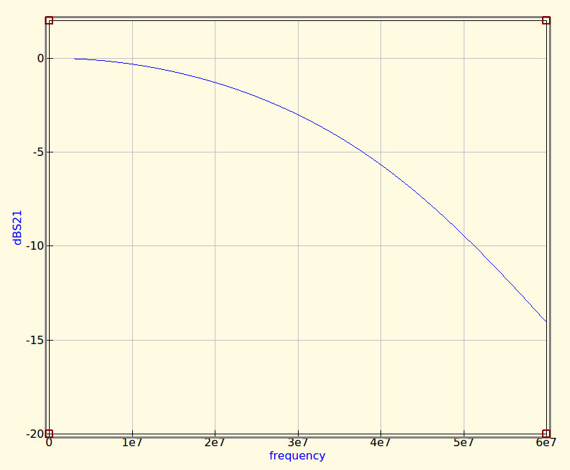
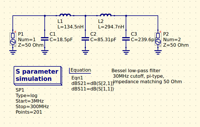
The filter we’re designing is simple enough, a 5th-order Bessel filter, and the software is the easy-to-use QUCS package on an Ubuntu Linux machine. Plug in the required figures and it spits out a circuit diagram, which we can then simulate to show a nice curve with a 3dB point right on 30MHz. It’s an extremely idealised graph, and experience has taught me that real-world filters using these designs have a lower-frequency cut-off point, but for our purposes here it’s a good enough start.
As previously mentioned, the component values are not preferred ones from a commercially available series, so I can’t buy them off the shelf. I can wind my own inductors, but therein lies a whole world of pain of its own and I’d rather not go there. RS, Mouser, Digikey, Farnell et al exist to save me from such pits of electronic doom, why on earth would I do anything else but buy ready-made?
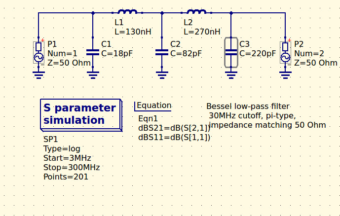
So each of the components in the above schematic needs moving up or down a little way to a preferred value. What effect will that have on the performance of my filter? Changing each value and re-running the simulation shows us the graph changing subtly each time, and it can sometimes be a challenge to adjust them without destroying the filter entirely. Particularly with the higher-order filters with more components in the network you can observe the effect of individual components on the gradient at different parts of the graph, but as a rule of thumb making values higher reduces the cut-off frequency and making them lower increases it. In my case I always pick higher values for that reason: my nearest harmonic I wish to filter is at double the frequency so I have quite some headroom to play with.
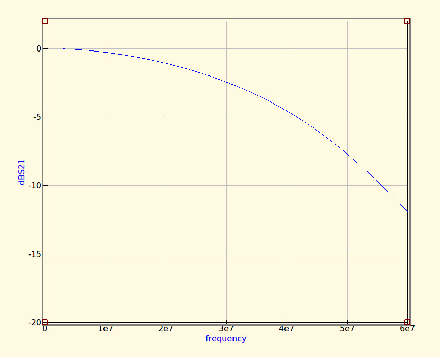
Having replaced my component values with preferred ones I can run the simulation again, and I can see from the resulting graph that I’ve been quite fortunate in not damaging its characteristics too much. As expected the cut-off frequency has shifted up a little, but the same curve shape has been preserved without any ripples appearing or it being made shallower.
If I were using this filter with a real transmitter I would ensure that I designed it with a cut-off at least a quarter higher than the transmission frequency. In practice I find the cut-off to be sharper and lower than the simulation leads one to expect, and for example, were I to use this one with a 30 MHz transmitter I’d find it attenuated the carrier by more than I’d consider acceptable. It must also be admitted that changing the component values in this way will also change the impedance of the filter from the calculated 50 ohms, however in practice this does not seem to be significant enough to cause a problem as long as the value changes are modest.
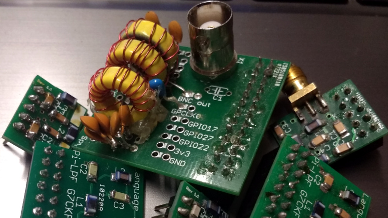
We haven’t made this filter, but in the past we’ve featured another one I did make, and by coincidence it was in the same frequency range. When I wrote a feature on automating oscilloscope readings, the example I used was the characterisation of a 7th-order 30 MHz low-pass filter. It might even be one of the ones in the header image, pulled from my random bag of filter boards for the occasion.


I have always been just a little confounded by the overlapping concepts of cutoff, power transfer, and impedance matching, all effect of the same filter at the same time. I can handle the ideas of any by themselves, but all together, they have the potential to be confusing. I used to look at old schematics for old GR Rangr and Motorola Micor radios that were constructed mostly without ICs, and just try to contemplate all the things happening in the RF areas.
I appreciate this basic tutorial, and would really appreciate a follow-on showing the construction of a coil, including the software tools involved and construction techniques.
Question for Qucs users: I have a circuit which uses AC simulation to sweep a frequency interval, with plots of current, voltage and (equation) power.
I’d like to change that to use a fixed frequency (can do: set the frequency in the supply voltage) and sweep one of the parameter values – the variable capacitor in the circuit.
The “parameter sweep” wants a simulation to work from, and the AC simulation is probably not what I want because it’s a fixed frequency, but setting up a DC simulation doesn’t seem to work – it invalidates all the voltage measurements.
What am I missing? It’s a simple LC attached to a source. How do I set up a parameter sweep for an LC so that I can plot the voltage and current measurements on the components?
(Was just about to ask this online, figured this would be a better targeted audience.)
You can also do it as a AC simulation with 1 point. That would imho be the best approach.
Set the AC simulation, as master for the parameter sweep. The AC simulation runs once, then the parameter sweep increases and the AC simulation runs again. If you should get a jacobian error when simulating, then try changing the number of points in the simulation.
Zero and one are not valid point values, but 2 is. Setting that, all my diagrams show a vertical line – indicating that the AC sweep is being graphed, not the parameter sweep.
No amount of fiddling with the (cartesian) displays change the “independent” axis. I can’t choose the independent axis by adding a new display, and all the voltage values show as “dependent” on “acfrequency”, not the swept parameter. (The swept parameter shows up as an available “independent” parameter, I can select it as a graphed Y-axis variable, but can’t make a display that uses it as the independent X-axis parameter.)
I also tried setting the AC sweep to “constant” – same results.
I’m of the opinion that it’s just something you can’t do in Qucs. You can parameter sweep a DC sim, but not an AC one.
For a sweep of cap values in a fixed-frequency simulation, you might want to try a transient simulation. I just tried what you described. It worked.
I have a source in series with an L, C, and R. I have voltmeters across the L and C, and an ammeter in series.
Transient simulation is time and cannot be changed, so I set it up as linear, 0->1 mS with resolution 100uS, the default.
Parameter sweep points to the transient sweep, parameter is CPlate, which is the “C” value of the capacitor, and endpoints are 5.5pF to 5.7pF with an appropriate step.
Simulation still doesn’t work – the voltage probes have no voltage values (normally “VL1.v” for inductor voltage, VC1.v” for capacitor voltage, and so on.
I’m honestly baffled. How exactly did you set up your transient sim to get voltages and currents to work?
Did you fill in the field in the “sweep parameter” named Sim= ? This should be set to the name of the transient simulation. On my setup, the default name was TR1.
I did. I’ve been playing around with this for about 10 hours trying out things and looking online.
I’d really like to figure this out – can you DM me on the Hackaday.io site so we can talk offline?
https://hackaday.io/PWalsh
Nice introduction to using Qucs for designing filters.
It is probably also worth mentioning that you can use sub-circuits in Qucs to create model components. For RF filter design, this is handy because you can create non-idealized models for your R/L/C passives that contains parameterized parasitic elements to achieve better transform results for real components. This is especially true as frequency increases. One related tip is to make the parasitic elements visible on the schematic to make them easy to edit between runs.
My thoughts exactly; the schematic is a few components short. At bare minimum the inductors should have some parallel capacitance and the capacitors should have some series inductance. For extra credit, add some parasitic resistance too. Reentrance is a huge pain in the ass with harmonic filters, and those parasitic elements will start to wreak havoc a few octaves above the cutoff frequency. Many manufacturers publish convenient S-Parameter files for their components, and muRata has a great tool for coming up with reasonable models for their caps that include parasitic elements.
Yes, the s-parameter files are available for many components these days. Johanson Technology also has many touchstone files here: https://www.johansontechnology.com/s-parameter. This is what I usually do if I can find the needed files from the manufacturer. For those interested in this, just follow the steps shown in this article, but replace the components with 2-port s-param components (for 2-port devices like R/L/C) under the “file components” section in Qucs. You can point to the correct s-parameter file under properties for each block. Make sure to look in the text of the touchstone / s-param files to see what the frequency range that they characterized is and make sure your s-parameter simulation stays within those bounds for correct simulation. You can also use this technique to introduce your own components like micro-strip based planar filters, etc if your field solver / simulation tool can generate touchstone files.
Another great one, Jenny, I’ll have to get a copy of that software and play.
But protip – if you have a lathe, winding coils can be fun! I use the threading settings on mine to get just the right turn spacing on whatever form I have clamped in there (I’ve used beaker and pickle jars as well as more conventional things for high power – drilling mounting holes with a diamond saw is actually pretty easy).
The jig is simple and obvious – two pieces, one of which is just a piece of wood in the tool holder, with a slit in one end, about halfway through, to guide the wire – I set this up so the end of the stick is really close to the work.
The other piece is a big L that holds the coil of wire I’m going to wind.
I set the lathe to 50 rpm and use the jog button, while tensioning the wire a bit with the other hand if that seems wise. Hot glue holds the stuff on the form till I dismount it and do something more permanent, but duct tape also works.
One quick comment on QUCS; make sure you download and study the PDF tutorials from the main website and ignore the built-in help text. The former is very much expanded and a very good introduction to the amazing power hidden by the QUCS UI. The latter should just be deleted as a confusing distraction from where the real action is.
I love QUCS a whole lot and I’m getting better at it all the time :) IMO it’s a good alternative to ltspice, and once you add in the optimisation function and octave back-end (another tool any serious EE should know – or at least Matlab) you have a very good framework for de-risking non-trivial designs.
I recently had a bit of a kerfuffle about the LPF I was using in my GPSDO. A friendly customer figured out that it wasn’t the actual LPF that was causing trouble, it was a combination of insufficient bypassing on the clock fan-out chip and ground loop on the two output cables. The solution was adding another 10 µF of local capacitance on the chip’s supply and wrapping the output cables around toroids to make common mode chokes (or just use one of the two outputs and leaving the other disconnected).
Continue Reading →
Please
I did a little bit of filter design for my internship this summer. We used Coilcraft parts for the inductors as they have a really great part selection tool https://www.coilcraft.com/apps/finder/rffinder.cfm
They have a pretty good parts sampling program as well.
It should be noted that the nominal value of the inductor can be very different from its actual inductance at that frequency, so in some cases the next size of inductor up or down may be better for a particular circuit.
Adding an option to the software to automatically design with preferred values would make a good student project.
Looking at the photo of one of your RasPi filters, I thought you should always have inductors at 90 degrees to each other, if they are close, to stop the magnetic coupling between them?
I understand the beauty of metal core toroid’s is that so much of the magnetic field is contained in the core that mutual coupling isn’t an issue. I’ve seen some radios with shielding between lowpass filters for each band, but each toroid is lined up just like the picture.