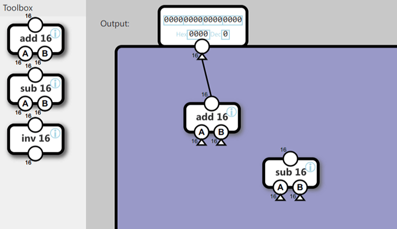
A rite of passage for a digital designer is to build a CPU. That may seem a formidable task and if you are thinking of building a modern CPU like the one in your PC, it is. However, a simple CPU is well within the reach of anyone who can sling some logic gates or HDL. We’ve even seen CPUs built in Minecraft. Now you can play nandgame and build a CPU step-by-step in your browser.
The game is based on the popular From NAND to Tetris site. True to the name you start out with a single NAND gate as a tool. From there you build an inverter, an AND gate, adders, flip flops, registers, and the like. You get a little help from the accompanying text and there are some blacked out hints if you get stuck.
The site notes that it is not complete yet, and we presume it means there should be more explanatory text. By the time you are building the ALU and instruction units, the text is a little sparse. However, it is a great way to experiment with how a CPU works internally and it is sort of fun, too.
We only had one real complaint. There are a few things that are made unnecessarily difficult because there is no way to get a solid logic 1 or 0 into the design — something that would not be true in real life. In addition, the feedback loops used to build flip flops isn’t very practical either, but at least it doesn’t make the game more difficult than real life. But it would be nice if they noted that in real life you’d have trouble doing as they suggest.
A lot of the custom CPUs we’ve seen on FPGAs are just toys. But two come to mind that are not. [Robert Baruch] has a custom CPU that can play Zork. We were very impressed with [F4HDK’s] A2Z computer which not only sports a powerful custom CPU, but also has an OS, a file system, and a set of utilities.


“A rite of passage for a digital designer is to build a CPU. ”
Team. Lots of breadboards. x86 something.
MHRD is supposed to be based upon NAND to Tetris.
tried it, fun. but it’s more like a puzzle than designing a cpu, the exercises are too “guided” to actually design a cpu. you have to build specific blocks and at the end just assemble them. I found that upgrading a given design to add, as example, new instruction, or try to reduce the cycle count for given instructions is way more interesting an rewarding. nice puzzle through
“edit”…
great job by the way, it’s really nice
Yes you have to meet their design spec and there’s often only one real way to do it, although there is some latitude. I had thought the same thing though. It would be cool to have a palette of all the modules you built and let you build whatever you wanted with it.
I know this is a few years old and all, however, I agree with your sentiment. A little while back, I have found a nice little alternative that is very engaging. There are pros and cons to it but it is very versatile in what it can do. I came across a Game on Steam that fits this desire and that is Turing Complete. As for learning there is something to gain although the way the game is implemented it doesn’t model the real world in how the actual electronics at the circuit level are designed and there are some limitations to it. For example, it doesn’t allow for any circuit you build to have circular dependencies. You can not make a basic latch from a set of NAND or NOR gates. So this could be a limitation on the “learning side of things”. Also there’s more to this about not modeling a real world CPU but will be noted later.
It is a game so there are challenges involved and this is what the developer intends. You start off by solving puzzles at the logic gate level, but as you progress through the challenges you start to build inner components of a given CPU such as half adders, full adders, counters, bit shifters, comparators for all of the ALU internal operations. There are also components that you learn to build after solving more of the puzzles for the memory components such as a register, ram, rom, register file, etc… Then as you move up through the basics then you get to the CPU Architecture levels where you begin to solve more puzzles to link the pieces together to make a simple working CPU. Then you begin to add more components to the CPU and are tasked with solving simple problems such as addinging a set of registers or a register file. Then in the next section of the game, CPU Architect II there are more puzzles for you to solve but at this stage there is a major rework to the underlying CPU design. Then you begin to add in conditionals, ram module as opposed to just the program rom, a stack, etc… Once you complete this set of stages or when you first reach it then the game unlocks and allow you to use any and all built in components that you can use in the Sandbox mode of the game. Some of these can not be used within your solutions to solving their puzzles. And the latter puzzles sort of step away from the actual Hardware implementation although you may have to refactor a bit here and there and it transitions into the Software side of things at the assembly – ISA level.
Here at this stage, you have to manually set the OPCodes for each and every instruction that your CPU will perform. Also, it has a built in assembly editor and this is where that is done. On top of that, you not only have to set the actual opcodes, you have to also give each of your instructions their own assembly mnemonic name. Then in the Assembly editor it also poses as an Assembler where you can write your assembly language and run your programs. It also has a built in debugging system for setting breakpoints, you can link various components or registers within the hardware that will show up in the Assembler so you can watch your values. You can run the program or even step through it. I’ve enjoyed many hours in this game. However, going back to not being a 1:1 model of the real world, the way it runs your source code is not the same as in real world practice. The game is based on tick counts where each single tick is a single cpu cycle instruction or operation. Where in the real world, we don’t just have a tick, we also have a tock. Real CPUs have a clock with a duty cycle that has a high and low state, and most CPUs also have micro instructions. Yet I found this game to be fun, engaging and rewarding to say the least and I have learned a little bit from it as I already had some basic prior knowledge beforehand. The biggest takeaway that I gained from this game was the ability to implement a stack in the hardware and setting up the opcodes for the stack pointer as well as push and pop commands. So there was still something to be learned from this experience.
Here’s a link to the game’s store page: Yes, it’s not free but definitely worth the purchase!
https://store.steampowered.com/app/1444480/Turing_Complete/
I wonder why they skip the humble Nor gate…
Though, their method of incrementing a variable is pure stupidity if one were to use it in a real design…
There are though far less circuit intensive methods of doing it if one wants to not use the full adder and a simple constant.
But for most systems that doesn’t do out of order execution, or work on multiple instructions in parallel, then using the full adder and adding a 1 to the start is fairly basic and will save one a lot of transistors. Having a dedicated instruction to increment or decrease a variable is nice, but there is very rarely a need for making dedicated hardware for it. (Other then a little glue logic to decode the instruction.)
It is a neat little game, but I wouldn’t recommend it as a learning tool.
I mentioned I didn’t like the way they handled that either. However, I could see doing this with a little lecture help with students for the first day of a unit where I would have them build their own real CPU. It kind of takes the edge off of it, I think, even though I agree I wouldn’t have made some of the design choices myself.
Because it is based on a popular book, NAND to Tetris.. Google it, it’s very neat!
I have never understood why nand gates gets all the glory….
Nor and Xnor can also do it.
Xor gates can do it as well. (in practice, on paper one needs at least a source for a logic high to be able to do it)
And even the humble Not gate can technically do it in practice as well, if it only has a pull up or pull down capable output. (Here some people might notice how our interconnections now becomes AND or OR gates depending on the not gates around the wire.)
And if someone feels like commenting that “that doesn’t work.” then go and try. (The humble diode is a nice way of making the standard hex inverter only capable of pulling its output to one state, in case one doesn’t have a “fancy” not gate in one’s drawers. Otherwise a handful of transistors and a bunch of resistors does wonders.)
look at the physical layout of a nand gate compare to a nor gate or a xnor gate.
That is your answer.
I admire the skill of producing this, and the goal of teaching people how to do logic design.
But we stopped doing digital logic with gates and schematics back in the 90’s. Get them started using an HDL. Even a simple pidgin language would be better than messing around with all that manual wiring.
do people design actual chips using HDL? Or do they design it with gates and schematics?
I always thought HDL was only for FPGA. To make a functional hardware tool with generic hardware. Or using it as a proof of concept using FPGA before going into high cost production/deisgn of a real chip.
Back in the 80’s, I did VLSI chip design by pushing rectangles of silicon, oxide and metal around. I doubt that’s done much anymore, except possibly for specialized leaf cells or analog designs. Now its mostly HDL and the software translates it to a physical structure. [Here](https://ocw.mit.edu/courses/electrical-engineering-and-computer-science/6-973-communication-system-design-spring-2006/lecture-notes/lecture_5.pdf) is a high-level view of chip design from a few years ago.
There’s a game called Silicon Zeroes which is a very similar concept, though it starts at a somewhat higher level of abstraction.
Steam has a game called Turing Complete and it’s quite engaging, satisfying, and rewarding.
Here’s a link to the game’s store page: Yes, it’s not free but definitely worth the purchase!
https://store.steampowered.com/app/1444480/Turing_Complete/