There’s a lot you can tell by looking at the waveform of your mains power. There are harmonics, transient changes, and periodic fluctuations that are correlated to the demand on the grid itself. Frequency shifts will tell you how fast or slow your clocks are running, and someone probably has a poorly isolated power line communication thing somewhere in your neighborhood. There’s a lot you can learn by looking at the waveform coming out of your outlets, but how do you tap into that? [David] is doing it with a PC sound card and some really interesting hardware.
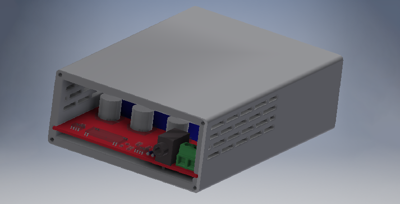
The Grid 2 Audio module is [David]’s entry to this year’s Hackaday Prize, and it consists of three main parts. The first is the mechanical part of the design. This comes in the form of an IEC power socket with a built-in switch, fuse, and illumination. Of course, you could simply buy one of these, but [David] is teaching himself Autodesk Inventor, and you have to start somewhere. The second part of this build is the PCB power supply and mains input. This is basically a pair of transformers, a PCB, and a whole lot of isolation to make this a safe board. The third part is a signal conditioning board that sends the waveform to a 3.5mm jack, for easy processing with any audio capture hardware.
The hardest part of this board is, by far, the PCB design, and for that [David] went all out. There are some big, meaty traces on this thing and real separation between the high voltage and low voltage portions of the board. The end result is something that sends the mains waveform to an audio card for easy processing with MATLAB, and all the goodies that come from that.


Wouldn’t a single transformer perform the same function, with a lot less hardware? Line voltage in, audio out. Use a 6.3v “filament” transformer, and reduce the output level with a potentiometer? If you want to go nuts, add a fuse on the input side, maybe some MOVs as transient suppressors, though that would be filtering out information you might want.
A power transformer generally is not very linear so there will be added distortion. How I would have done it is with some sort of transmitter – probably Bluetooth, Wifi, or FM – with a capacitive power supply to power it and a voltage divider to sense the mains.
Power transformers act as lowpass filters because the core is not suitable for passing high frequency signals. There’s a hysteresis effect going on that blocks the high frequency content.
I’ve found strange signals with an RF Explorer that I didn’t realize were localized to the power outlet. I haven’t analyzed when placing the antenna near and using something more sophisticated or even Audacity or a freeware SDR application.
I wasn’t sure if the water lines or the power outlets were the source of some of the signals the day I was sweeping… though still wonder since water mains, power mains and I speculate other “pipes” can resonate and carry the lower frequency signals even further.
Interesting is I’ve speculated that cable and phone lines can do the same and interesting was finding this Great Scott! demonstration:
https://youtu.be/cz3DEP2LC_w
This seems like a potential device that can be used to communicate through the power lines I’m thinking with a transmitter. Could be used as a relay or that type of project also if low enough frequency or within the ISM guidelines. Reminds me of this VLF/ELF/ULF system for communication through the water lines (pg.45 or publication pg.49): http://www.americanradiohistory.com/Archive-Elementary-Electronics/1970/Elementary-Electronics-1972-05-06.pdf
With power lines, I’ve observed into the MHz signals.
At least in the US the water pipes in your house are *bonded* to the nuetral/ground lug in your main electrical panel. Gas pipes are supposed to be bonded as well, but many are not in older homes. So your signal noise could be propagating through all three.
The NEC has shifted to calling this bonding instead of grounding so that people will know that you can’t just drive a ground rod or two anywhere and call it good… It has to be connected to the main panel with an unbroken conductor(no splices/junctions) for full protection.
The idea is that if a live wire comes into contact with either gas or water it will short to ground and trip the breaker instead of waiting for a meat sack to touch it and get friend as they complete the circuit.
I haven’t swept at the house I’m working on in detail other than with the mini-bat detector and a microphone. Not getting the body assault issues there so much all the time post Cuban Embassy issues coming out or this U.S. administration. The sound and signals issues still do occur… though more mild other than the directed to me or the vicinity communications sound layering on environmental noises. I was at a hotel when I did the sweep I noted above in more detail back in 2015-16.
When I read into the latest code requirements maybe fall of 2016; I discussed with code enforcement and with the power company and realized the gas line bonding needed to added and same goes with the modern rods connected directly to the main panel where the ground rods were placed 16ft apart for the min sphere of influence as well as meeting other code specs with a ground bridge line added also for the cable, TV, et.al. devices.
I was surprised when I found the local power company didn’t want the meter panel/box grounded for some reason and found they had cut that.
I wonder with power lines and even the boxes… if they can be shielded more to avoid losses since there are high magnetic fields around even a household breaker panel. Doesn’t help having a transformer in the front yard with a city water line and a cable/phone box. Reminds me of the transatlantic cable having such high losses until Mu-Metal was invented and implemented.
[image: Family%20Hub_GNB%20Flyout.jpg]
That Isolation clearance doesn’t look like it’s wide enough. Supposed to be at least 6mm.
“and someone probably has a poorly isolated power line communication thing somewhere in your neighborhood.”
given the bandwidth of those devices i don’t think you’ll be picking up anything when sampling at 44kHz, also if you don’t band-limit the signal (nyquist), aliasing will give a distorted picture too.
now i wonder if the PC sound-card will have a low-pass stage itself ?
also now i want to hear the signal with the 50/60Hz removed (and maybe transposed up a bit) when i turn on/off the washing machine or tv’s computers ..
i doubt we’ll hear anything ..
Yes, the soundcard (heck, even the ADC itself) has a sharp low pass filter, otherwise you’d have aliasing effects from interference all the time
Yea my thought on doing this would be a series of filters to get rid of the 50/60Hz stuff, and then get it into something like an RTLSDR but I don’t know how you’d design it for that with any kind of safety. I’d imagine you could do some kind of high pass capacitive filter but the signal level of the mains power is going to be insanely larger I’d think. maybe have to have the roll off start at a few 10s of kHz to get it to drop enough by 60Hz to not overload the sdr?
Or, if you really just want to “listen to mains power”, there is this:
https://www.musicsupply.com/item.php?p=11&cat=7&returnpage=shop.php%3Fcat%3D7
In addition to lots of troubleshooting of audio equipment, I _have_ used one to listen to the amount of noise being introduced into the power line by some lighting dimmers.
Question: If you tapped something like this into a local mains circuit, lets say an accommodation unit for about 50 men, would you be able to detect the usage of a home-made tattoo gun?
After lights out, maybe, if there’s all sorts of other loads, going on and off, laundry, lights, TVs etc, doubtful.
TVs are small LCD models, shenanigans usually go on after lights out/lockup. Laundry is not done after lockup either. I understand that a tattoo gun would be an inductive load, unlike anything else on the system after lockup? Would need to check if HVAC and water heating runs on the same circuit. I guess an experiment or two may be worthwhile…
Asking from a health perspective, hepatitis C is rampant the these types of facilities and tattooing is definitely a vector. They primarily use burnt plastic ash mixed with shampoo for ink, I have seen tattoos over a year old that have not healed.
Yah, you should theoretically see the current lagging from the inductance,
(Relevant power factor stuff) https://www.meddeviceonline.com/doc/an-introduction-to-power-factor-how-to-control-it-in-your-med-device-design-0001
But it’s such a low powered device in a large facility that corridor lighting etc could swamp it out.
One solution would be to provide clean needles and ink to these gentlemen. It might sound like a joke, but would help your health issues a lot.
Courtesy of a web search:
I’m guessing your tattoo gun is probably built from a hair/beard trimmer.
I understand that tape decks were robbed of their motors to build tat guns too.
As a kid, There were two of those old vibrator~buzzer type hair clippers in my house.
One unit was (relatively speaking) fairly smooth running and quiet. The 2nd unit was noisy and vibrated your hand.
The acoustically noisy one would cause a bit of video noise in the TV ( this was with strictly “over the air” analogue reception.
Too bad I tossed out both clippers, many years ago, or I could look at them for any built in ringing/spike suppression attempts.
I have a suspicion that a vibrator type unit would have a fairly steady~consistent signature on the power line.
Perhaps some of the cabling & network techs could chime in here??
I would think that the resolution of the test gear would have a strong influence on being able to see the noise.
I’m guessing the resonance of a buzzer would play a part in any shift/lag in the noise peak.
One for the cable techs again, But depending on how the circuits are run, joined and “terminated”, would you see any noise reflection bounced in the wiring?
Isn’t the sound a real giveaway?
I need to build myself one of these. My AC Lines are full of noise and this might even help me find my noise on the 6m Amateur band.
It reminds me of a documentary I saw about mains power, how the signal is unique and can be used to date recordings by looking at the mains hum. Fun stuff.
Energy Disaggregation.
https://web.stanford.edu/group/peec/cgi-bin/docs/events/2011/becc/presentations/3%20Disaggregation%20The%20Holy%20Grail%20-%20Carrie%20Armel.pdf
It’s close but not quite what I mean, though also very interesting. At any one time the signal of the mains is unique due to the usage in the local area. It’s kind of a finger print that can be used to correlate a hum in an audio recording on a certain day and time of day, if you have a long running mains recording to check against (I’m sure some people do).
I’m a firm believer in tracking time of day by the mains noise!
Before we were swamped with, ’round the clock, cell tower emissions, I used to wait till the late night~pre-dawn hours to indulge my music listening urges.
Alas, it’s become tough to find a time when something isn’t bleeding into my PC sound or land line or stereo nowdays.
Upgrade to the new age of digital audio, using fiber for unmatched EMI resistance.
imqqmi – Here’s something on the topic; https://www.bbc.co.uk/news/science-environment-20629671
Love the “7mA SHOCK” warning
What no video? Whats the point.
It is a lot easier just to use isolated amplifier like TI AMC1200 and get rid of voltage transformer. The only thing is to get isolated power supply for hot side, but there’s a lot of solutions for isolated low power DC-DC converters.
I used 3 turns of wire on a big mains transformer (just wrapped it around) and hooked it to the microphone input of a mixing desk that conveniently has a USB audio interface for recording. I used a software called “Praat” to do spectrum analysis to analyse our ripple control.
Use a high frequency transformer with a cap in series to limit the current at 50/60hz. A mains transformer has a high attenuation above 400hz or so