Implementing PoE is made interesting by the fact that not every Ethernet device wants power; if you start dumping power onto any device that’s connected, you’re going to break things. The IEEE 802.3af standard states that the device which can source power should detect the presence of the device receiving power, before negotiating the power level. Only once this process is complete can the power sourcing device give its full supply. Of course, this requires the burden of smarts, meaning that there are many cheap devices available which simply send power regardless of what’s plugged in (passive PoE).
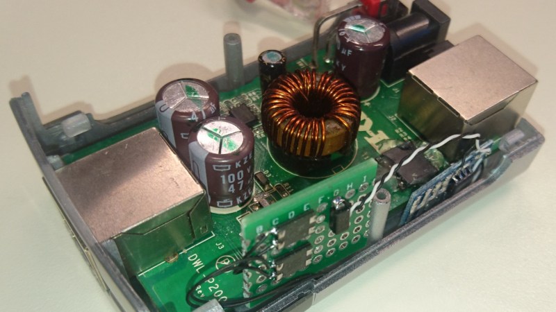
[Jason Gin] has taken an old, cheap passive PoE splitter and upgraded it to be 802.3af compatible (an active device). The splitter was designed to be paired with a passive injector and therefore did not work with Jason’s active 802.3at infrastructure.
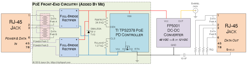
The brain of the upgrade is a TI TPS2378 Powered Device controller, which does the power negotiation. It sits on one of two new boards, with a rudimentary heatsink provided by some solar cell tab wire. The second board comprises the power interface, and consists of dual Schottky bridges as well a 58-volt TVS diode to deal with any voltage spikes due to cable inductance. The Ethernet transformer shown in the diagram above was salvaged from a dead Macbook and, after some enamel scraping and fiddly soldering, it was fit for purpose. For a deeper dive on Ethernet transformers and their hacked capabilities, [Jenny List] wrote a piece specifically focusing on Raspberry Pi hardware.
[Jason]’s modifications were able to fit in the original box, and the device successfully integrated with his 802.3at setup. We love [Jason]’s work and have previously written about his eMMC adventures, repairing windows tablets and explaining the intricacies of SD card interfacing.


Looks very similar to the wisdom implemented with level 1 and 2 Electric Vehicle charging stations. You would have a relay switch controlled at the mains source by a small controller there and a similar unit in the car, also with its own relay. Only when both controllers are talking and happy with each other will they choose to close the relays and let the power flow.
A good idea is often useful elsewhere. I can fully appreciate why they are also doing this in POE.
While 802.11af (PoE) used specific resistances on specific pairs to show PoE compatibility (an easy way for an unpowered device to communicate over a wire), newer standards such as 802.11at (PoE+) are able to use the Layer 2 protocol LLDP to negotiate wattage in 0.1 watt increments.
I dipped my toe into POE when installing cameras at my little workshop, what a headache, I understand “proper” POE is 48v DC riding on the signal wires and brought out via centre taps on the coupling transformers, but so many “POE” adapters, cameras, switches just fire 12v down an unused pair on the cable, the two being uncompatible, yet both advertised as “POE” . I suppose technically they are but it was a right pain.
/rant.
The original standard for PoE (802.11af) was 48VDC give or take about 10 volts.
Later standards such as 802.11at (PoE+) tighter tolerances, but to maintain backwards compatibility with 802.11af, the maximum supported voltage at the powered device has remained at 57 volts.
The PoE variants in the 802.3bt standard are functionally similar but provide higher current.
Anything providing less than 37 volts at the device end of the cable doesn’t comply with any PoE standard.
Pedantically speaking just because it isn’t compliant with a standard doesn’t mean it isn’t accurately described as PoE. I spliced the power cable of a cheap 10/100 network switch I was putting in my attic into the unused lines on the CAT5 running through the walls. It’s not compatible with anything else but I’m still delivering usable power over ethernet connections.
For the benefit of OTHERS (not you) standards and names go hand-in-hand. If someone else was working with your hack and didn’t know anything about it, there might be problems.
Agreed.
it may be *grammatically* described as PoE, but is it not the thing called PoE.
Here i try to always remember to ask where the thing is/will be connected, to ascertain if it is really PoE or what i tell the person is “fake poe”.
Or, in many cases, I describe ( really, in writing or spoken form ) as “those thing that puts the power supply at one end of the network cable and send 12V through the unused pairs “.
Because there is always those people that will feel the need to tell you that “PoE means power over ethernet”.. To those I offer, when possible, to test connect their appliances to a PoE 48p switch, and if the thing doesn´t work then I am allowed to put it in the trash and they will buy the equipament I´m suggesting. Interestingly, many seem to rethink what their beliefs about PoE are … :)
You are running power over an ethernet cable, what sort of voltage, how much power? unspecified.
But you are not abiding by the PoE standards(802.11af etc etc) and therefore it’s not certified/accredited PoE nor should it ever claim to be, there is a difference.
Give or take 10V = Frying tonight! lol
> POE is 48v DC riding on the signal wires
Yup…This is why i’m scratching my head about the above circuit diagram, specifially the two bridge rectifiers, they are utterly pointless.
no installation is perfect, you have to expect crosover cables and unitentially crossed wiring (“A” and “B” standard)…the rectifiers allow the device to correctly extract power and function, as opposed to shorting the power or bursting into flames :P
This is why you get panels in pairs from the same manufacturers, so that both ends have the same wiring standards.
Plus crossover cables are obsolete since…ages if not decades. Auto-MDIX is best MDIX.
But i do see your very valid point.
bridge rectifiers are cheap ways to protect expensive toys :D
It’s part of the PoE standard since the powered device (PD) can’t necessarily assume that the cabling is only straight-through. Adding the diode bridges is an easy way to prevent devices from being damaged through reverse polarity (it also means the manufacturer doesn’t have to bother with RMAs from this type of damage either).
Also, while we’re at it, the above circuit diagram will not support GBit ethernet, as it’s missing two transformers.
PoE and the bt standard will allow up to 90W, and proprietary (non-IEEE) gets just shy of the maximum allowable under the NEC class 2 low power circuits (100W). A lot of vendors including MicroSemi, and PhiHong are in this space. Get ready for the digital ceiling where lighting and most things fan out from a PoE power box. Plug and play lighting. No electrician required (depends).
Already a thing in business. Combine with VLC (Visible Light Communications) and you have two problems taken care of.
Combine with a cube wall panel with cable bussing and connection and latching system and that’s three.