More Mirrors (and A Little Audio) Mean More Laser Power

Lasers are pretty much magic — it’s all done with mirrors. Not every laser, of course, but in the 1980s, the most common lasers in commercial applications were probably the helium-neon laser, which used a couple of mirrors on the end of a chamber filled with gas and a high-voltage discharge to produce a wonderful red-orange beam.

The trouble is, most of the optical power gets left in the tube, with only about 1% breaking free. Luckily, there are ways around this, as [Les Wright] demonstrates with this external passive cavity laser. The guts of the demo below come from [Les]’ earlier teardown of an 80s-era laser particle counter, a well-made instrument powered by a He-Ne laser that was still in fine fettle if a bit anemic in terms of optical power.

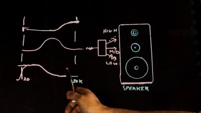
[Les] dives into the physics of the problem as well as the original patents from the particle counter manufacturer, which describe a “stabilized external passive cavity.” That’s a pretty fancy name for something remarkably simple: a third mirror mounted to a loudspeaker and placed in the output path of the He-Ne laser. When the speaker is driven by an audio frequency signal, the mirror moves in and out along the axis of the beam, creating a Doppler shift in the beam reflected back into the He-Ne laser and preventing it from interfering with the lasing in the active cavity. This forms a passive cavity that greatly increases the energy density of the beam compared to the bare He-Ne’s output.

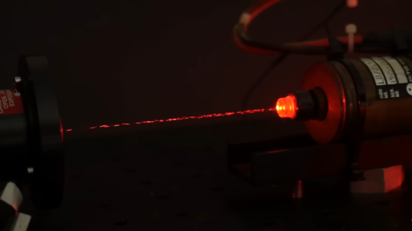
The effect of the passive cavity is plain to see in the video. With the oscillator on, the beam in the passive cavity visibly brightens, and can be easily undone with just the slightest change to the optical path. We’d never have guessed something so simple could make such a difference, but there it is.

Continue reading “More Mirrors (and A Little Audio) Mean More Laser Power”

Power Over Ethernet Splitter Improves Negotiating Skills

Implementing PoE is made interesting by the fact that not every Ethernet device wants power; if you start dumping power onto any device that’s connected, you’re going to break things. The IEEE 802.3af standard states that the device which can source power should detect the presence of the device receiving power, before negotiating the power level. Only once this process is complete can the power sourcing device give its full supply. Of course, this requires the burden of smarts, meaning that there are many cheap devices available which simply send power regardless of what’s plugged in (passive PoE).

[Jason Gin] has taken an old, cheap passive PoE splitter and upgraded it to be 802.3af compatible (an active device). The splitter was designed to be paired with a passive injector and therefore did not work with Jason’s active 802.3at infrastructure.

The brain of the upgrade is a TI TPS2378 Powered Device controller, which does the power negotiation. It sits on one of two new boards, with a rudimentary heatsink provided by some solar cell tab wire. The second board comprises the power interface, and consists of dual Schottky bridges as well a 58-volt TVS diode to deal with any voltage spikes due to cable inductance. The Ethernet transformer shown in the diagram above was salvaged from a dead Macbook and, after some enamel scraping and fiddly soldering, it was fit for purpose. For a deeper dive on Ethernet transformers and their hacked capabilities, [Jenny List] wrote a piece specifically focusing on Raspberry Pi hardware.

[Jason]’s modifications were able to fit in the original box, and the device successfully integrated with his 802.3at setup. We love [Jason]’s work and have previously written about his eMMC adventures, repairing windows tablets and explaining the intricacies of SD card interfacing.

Active Discussion About Passive Components

People talk about active and passive components like they are two distinct classes of electronic parts. When sourcing components on a BOM, you have the passives, which are the little things that are cheaper than a dime a dozen, and then the rest that make up the bulk of the cost. Diodes and transistors definitely fall into the cheap little things category, but aren’t necessarily passive components, so what IS the difference?

Continue reading “Active Discussion About Passive Components”

Universal Active Filters part 2 for Hackaday by Bil Herd

Universal Active Filters: Part 2

An easy way to conceptualize active filters is thinking about audio speakers. A speaker crossover has a low-pass, high-pass and band-pass effect breaking a signal into three components based upon frequency. In the previous part of this series I took that idea and applied it to a Universal Active Filter built with a single chip opamp based chip known as the UAF-42. By the way, it’s pretty much an older expensive chip, just one I picked out for demonstration.

Using a dual-ganged potentiometer, I was able to adjust the point at which frequencies are allowed to pass or be rejected. We could display this behavior by sweeping the circuit with my sweep frequency function generator which rapidly changes the frequency from low to high while we watch what can get through the filter.

In this installment I’ll test the theory that filtering out the harmonics which make up a square wave results in a predictable degradation of the waveform until at last it is a sine wave. This sine wave occurs at the fundamental frequency of the original square wave. Here’s the video but stick with me after the break to walk through each concept covered.

Continue reading “Universal Active Filters: Part 2”

Universal Active Filters Part 1

Universal Active Filters: Part 1

Today I am experimenting with a single chip Universal Active Filter, in this case I made a small PCB for the UAF-42 from Texas Instruments. I chose this part in particular as it facilitates setting the filter frequency by changing just a pair of resistors and the somewhat critical values that are contained on the chip have been laser trimmed for accuracy. This type of active filter includes Operational Amplifiers to supply gain and it supports various configurations including simultaneous operating modes such as Band Pass, Low Pass and High Pass make it “Universal”.

Filter Basics

Speaker Crossover Example

Looking at the block diagram you can see where I have inserted a dual-ganged potentiometer to change both resistors simultaneously which should allow a straight forward adjustment for our purposes here.

Looking into the components of a simple RC filter which can easily implement a simple Low Pass or High Pass filter, we see that the math is fairly straight forward and swapping the components with each other is all that is needed to change the type of filter. Continue reading “Universal Active Filters: Part 1”