It’s probably not much of a stretch to say that many of us have taken on a project or two that were little more than thinly veiled excuses to add a new tool or piece of gear to our arsenal. There’s something to be said for a bench full of button-festooned test equipment blinking away, it’s like bling for nerds. But just like getting your name written out in diamonds, it can get expensive quick.
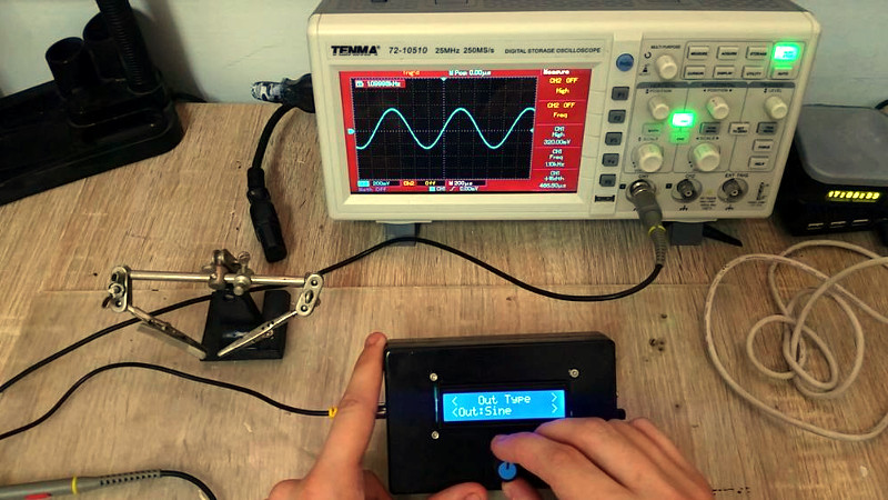
 Luckily, the hacker has enough technology at their disposal these days that DIY test equipment can help fill your bench without emptying your wallet. [Faransky] has created a very impressive Arduino function generator that doesn’t skimp on the features. Capable of generating sine, triangle, and square waves up to 10MHz with its all-digital circuitry, it’s a piece of gear that’s well worth the $30 USD or so it should cost to build your own version.
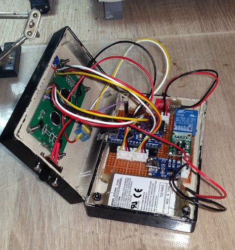
For those worrying that [Faransky] is relying on the PWM functionality of the Arduino Nano to generate waveforms, have no fear. At the heart of the device is a AD9833 waveform generator; with the Arduino, rotary encoder, and 16×2 LCD providing an interface to control it over SPI.
Unfortunately, the AD9833 doesn’t have a way to control amplitude, something which is pretty important in a function generator. So [Faransky] uses a X9C104P 100KOhm 8-bit digital potentiometer as a voltage divider on the chip’s output.
To wrap up the build, he added a 2000mAh 3.7V Li-Ion battery and TP4056 charger, with a DC-DC boost converter to get 5V for the Arduino. Though if you wanted to create a benchtop version of this device, you could delete those components in favor of a 5V AC/DC adapter.
We’ve seen our fair share of DIY function generators, ranging from minimalist builds to hardware that could pass for a commercial offering. We’ve even seen some cheap turn-key function generators, though the usual warnings about getting what you pay for apply.


For only little more ($69) you can get this (or one of the more modern versions with a graphic LCD):
https://www.banggood.com/MHS-5200A-25MHz-Digital-DDS-Dual-channel-Signal-Generator-Source-Frequency-Meter-13N2-p-1041328.html
25MHz, arbitrary waveforms, two channels and a built-in basic frequency counter. Oh and the USB protocol is known and there is open source software to control it too, along with some hw hacks and improvements.
DIY test gear is fine but it doesn’t make much sense when for the same cost (and labor!) you get inferior product.
Except for enjoying the designing, building and using your own equipment. But who does that here on Hackaday…right?
Jan has a point though, it always annoys me when I build something and then later find out I could have ordered it for a couple bucks from china… yes, of course you always learn something in the process but personally I’d much rather build something that would be difficult to obtain otherwise.
Looks like Faransky enjoyed putting the project together which looks well executed. GG Faransky. Keep building! Value is more than money.
As for the specs – I see loads of things reviewed/torn down by Dave Jones on his EEVblog channel that look fantastic on the specsheet that turn out to be total howlers. Not saying the mhs-5200a is good or bad – have you got one Jan? Is it as good as the advert?
I’m thinking more DIY learning gear that might also have a practical value along with the learned how to self make. Is interesting the the ability to buy so cheap from other places too and using modules built around chipsets.
Problem with this design is the digipot, they don’t have good bandwidth.
Hm. I suppose you could make one, from a load of resistors and maybe relays to switch between them at each stage. Like an R-2R DAC, except the input would be the signal in question, and it wouldn’t be able to swich fast (which wouldn’t matter here). That is what you mean by bandwidth, you mean for the signal travelling through it, not the speed it can switch “value” at? Relays are good enough to pass high frequency through right?
You wouldn’t necessarily need 8-bit, you could perhaps get by with 6, although once you’re building it, each extra bit doesn’t cost much (increasingly relatively less!), and doubles the precision.
I was thinking the problem is probably crappy sine and square waves. They are not easy to do well.
Everyone is saving money by using a computer interface. How many test instruments can run at once from one computer?
Depends on the instrument, if it’s using the host computer for FFTs and stuff, or even more complex. Though that’s really the analysis stage more than an instrument itself. Still, modern PCs are ludicrously powerful mathematically. It’s only the shitty software, with it’s endless levels of indirection and object-orientation, that make them run so slow. I used the ‘net fine, www too, on a 486-100 with 8MB RAM. Wouldn’t even be able to load Google now, but the web hasn’t really got much more informative or useful, proportionate to the thousands of times more CPU power and RAM it demands. Actually Facebook would be right at the opposite end of that graph.
/ramble.
Yeah so computers are powerful at maths. For instruments probably the USB bus’s bandwidth would be the limit, although USB3 is creeping into sight now. I suppose a few gadgets using USB3 might start to challenge the CPU (and it’s multiple internal CPU cores)) a bit if they were running flat-out, like perhaps a completely flat SDR with an input bandwidth of lots of MHz.
Actually really expensive instruments don’t bother with USB and use Ethernet as a high-speed way of getting data in. Ethernet’s always ahead of USB, but then it uses better connectors and wire, and has stricter standards, and no cheap garbage attached to the bus, so it would be. Actually it’s point to point so it isn’t really a bus.
I’m thinking of the cheaper test equipment, both commercial and home-grown open source. Likely to use USB2 or 2.1 at best. Stuff that maybe chokes on a 4 port USB hub.
I’ve had a few USB connected items that only work reliably if not connected through a hub.
“How many test instruments can run at once from one computer?”
I dunno, ask Hewlett-Packard about HPIB capabilities…
Well, in this case we’re talking about USB.
I have something very similar which was all of 12 USD last year. It had completely weird power supply requirements, so I DID have to build that in a way (also prolly why it was 12 bux). First thought I had when seeing the DDS sig gen.
This was a pretty cool read tho. I like finding out how things are done and I have already spotted a couple of mods I should apply to my sig gen now. Thanks, Faransky :)
I disagree. The design in the post is quite good for the cost. You can even drop it to $10 if you are ok with using just a PC connected arduino. And the 12 MHz that DDS can do is quite good for hobby level. You could make it more advanced by adding a DC shift and amplitude control, two opamps and two pots and a better supply.
On the other hand, that MHS-5200A does have some issues right from the start and depending where you live there might be some significant import taxes.
A function generator without a PLL, what a shame.
The NCO and phase modulator in the AD9833 perform that function. Even a PLL is only as good as it’s reference clock.
…. its reference clock.
Great job! I recently went down the direct digital synthesis rabbit hole (PWM doesn’t play nice with my application). Kudos for the clean project. Mine is still a rats nest…
no low-pass filter on the output ..
Does the AD9833 need one? This isn’t just an Arduino powering a DAC, it’s a function generator in a chip, the Arduino is only operating it’s controls.
Depends on what you’re doing with it. As far as I can tell, it has 10 bits of output resolution, so that might cause some high frequency noise on the output at -60 dB from the main signal.
Agreed. Should have a lowpass.
There are several Arduino-driven DDS projects (example: the Poor Hams Scalar Network Analyser). For a wider frequency range, AD9851 modules from Ebay are popular.
Troubles come if you start chasing accuracy. Binary DDS phase accumulators mean you either tolerate a weird frequency step, or generate a custom clock (178.956 970 67 MHz for a 1/24Hz step). That, in turn, takes you to TCXOs, clock chips like the si5351, and the rabbit-hole of oscillator stability / drift…