To say that the RTL-SDR project revolutionized hacker’s capabilities in the RF spectrum would be something of an understatement. It used to be that the bar, in terms of both knowledge and hardware, was so high that only those truly dedicated were able to explore the radio spectrum. But today anyone with $20 can pick up an RTL-SDR device, combine it with a wide array of open source software, and gain access to a previously invisible world.
 That being said, RTL-SDR is usually considered an “Economy Ticket” to the world of RF. It gets your foot in the door, but experienced RF hackers are quick to point out you’ll need higher-end hardware if you want to start doing more complex experiments. But the KerberosSDR may soon change the perception of RTL-SDR derived hardware. Combining four R820T2 SDRs on a custom designed board, it allows for low-cost access to high concept technologies such as radio direction finding, passive radar, and beam forming. If you get bored with that, you can always just use it as you would four separate RTL-SDR dongles, perfect for applications that require monitoring multiple frequencies such as receiving trunked radio.
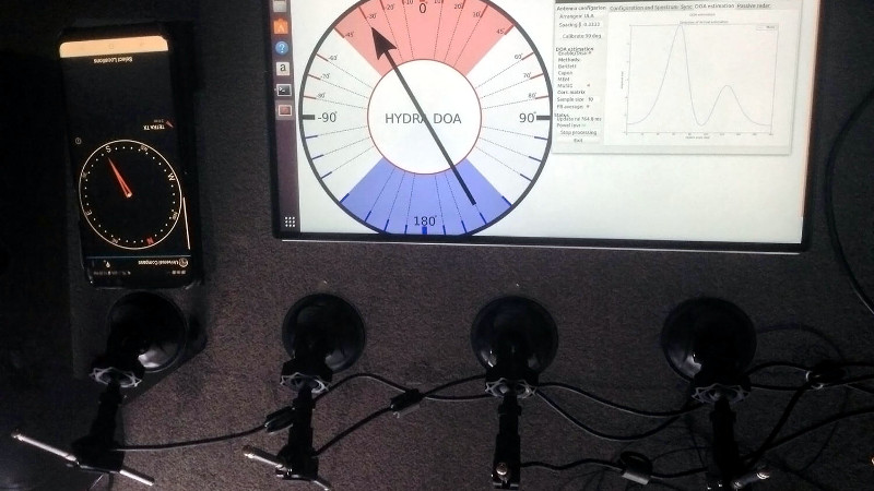
KerberosSDR (which was previously known as HydraSDR) is a collaborative effort between the Othernet engineering team and the folks over at RTL-SDR.com, who earlier in the year put out a call for an experienced developer to come onboard specifically for this project. Tamás Peto, a PhD student at Budapest University of Technology and Economics, answered the call and has put together a system which the team plans on releasing as open source so the whole community can benefit from it. In the videos after the break, you can see demonstrations of the direction finding and passive radar capabilities using an in-development version of KerberosSDR.
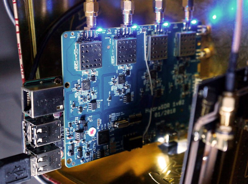
As for the hardware, it’s a combination of the RTL-SDR radios with an onboard GPIO-controlled wide band noise source for calibration, as well as an integrated USB hub so it only takes up one port. Everything is wrapped up in a shielded metal enclosure, and the team is currently experimenting with a header on the KerberosSDR PCB that would let you plug it directly into a Raspberry Pi or Tinkerboard.
The team hopes to start final hardware production within the next few months, and in the meantime has set up a mailing list so interested parties can stay in the loop and be informed when preorders start.
If you can’t wait until then, we’ve got a detailed write-up on DIY experiments with passive radar using RTL-SDR hardware, and you can always use your browser if you want to get your radio direction finding fix.


I bought the Tzumi MagicTV when it went on sale at Walmart in June.
https://hackaday.com/2018/05/30/cheap-stuff-to-hack-a-router-with-an-sdr-for-13/
I followed a blog on reddit where they were able to hack it.
https://www.reddit.com/r/RTLSDR/comments/8mlbps/tzumi_magictv_is_an_openwrt_board_rtlsdr/?sort=old
I was really hoping for it to be an SDR I could use, but it seems to me they only got it to run their own firmware to do the same thing the original did…
Kind of reminds me of those old-school TV tuner add-ons for handheld consoles like the Game-gear.
“they”, you dont buy unhacked stuff in hopes somebody will do work for you
besides as long as someone managed to boot custom firmware all the hacking is pretty much done at that point, what else were you expecting? nice GUI or something? pipe rtlsdr data to another computer and play with it
I understand your criticism, my skills are no where near those who did the hacking. I guess I was taken in by the optimism of the HaD article basically saying a new low cost SDR had been discovered on a device that was readily available (local Walmart).
“pipe rtlsdr data to another computer and play with it”
Ummmm, yeah…. So, you mean I use the Unix/Linux pipe command to do this?
From my post poisoned and gun shot wound head injury incidents… I can basically say from a layman perspective from the basics of systems analysis and application development think that all either command, procedural or object oriented programs are going to have the basic “Input(s)”, “Process(es)” and “Output(s)” or I.P.O. system steps. So from a system analysis perspective when dealing with different applications there may be the literal “pipe” Unix/Linux commands from the command line process where we’d need to find the outputs or variables for the memory if stored so can be accessed somehow like in a txt file maybe, data structure or even direct memory address(es) to be input and processed into the applications we prefer like with a GUI.
Might even need another application or dll (Dynamic Link Library) to do that translation process basically to get the data in the format we desire with additional functionality also if required.
https://www.rtl-sdr.com/rtl-sdr-tutorial-setting-up-and-using-the-spyserver-remote-streaming-server-with-an-rtl-sdr/
Thank you Sir!
Bookmarked.
How were all the receiver synchronized? I recall this being a issue when dealing with multiple RTL-SDR’s
My understanding is that all four devices share a signal clock for the tuner and rtl2832u:
1. connect to device 0 and start streaming I and Q
2. connect to device 1 and start streaming I and Q
3. connect to device 2 and start streaming I and Q
4. connect to device 3 and start streaming I and Q
5. switch all 4 devices from their antenna to an onboard common zener diode noise source.
6. switch all 4 devices back to their 4 individual antennas
7. Then using the samples with the common noise signal shared between all four devices you would use cross correlation to calculate the relative offset between each pair of signals. Circular cross correlation using FFT’s would be mathematically be the most efficient way:
a = fft(device 0);
b = fft(device 1);
c = a.*conj(b);
d = ifft(c);
And the index in “d” with the maximum absolute amplitude would indicate the number of samples offset between each pair of signals.
And a finer compensation could calculated to fully align the samples from each stream using Quadratic Interpolation Spectral Peaks to align with a greater granularity than just one sample. e.g. https://ccrma.stanford.edu/~jos/sasp/Quadratic_Interpolation_Spectral_Peaks.html using using 2 additional samples from “d” either side of the maximum.
And then everything after that is just using the phase coherent and phase synchronization samples.
In the past I’ve seen this done by providing a common master clock source to all the sdrs via an external clock generator and some cables of equal length. Hackaday has even posted some projects that do exactly that for passive radar using local radio stations as the initial source of the radio waves.
Regarding passive radar:
Perhaps the most robust signal of a local Continuously Operating Reference Station (CORS) that is part of a network of real-time kinematic (RTK) positioning base stations, broadcasting global navigation satellite system (GNSS) corrections, would be a good candidate for the baseline transmission as it also provides a standard time reference.
It reminds me of bi-static radar, a secondary receiver at a different location picks up the reflected signal from the main radar. The data of the second receiver is time correlated to the main radar’s azimuth and elevation at the time of transmit.
On first glance, that 4x SDR board looks mighty sweet. Any word on the clocking? 4 independent clocks or one synced? Would be a great little board to monitor multiple channels simultaneously if you could run 4 clocks.
According to the creators of the KerberosSDR, there is one clock (TCXO), but that does not prevent the devices from being tuned to any frequency, so one could be at 1090MHz (ADB-B) while another is tuned to 1575.42 MHz (GPS), and so on, they can be treated exactly the same as four independent RTL-SDR devices plugged into a computer.
“… If you’re not interested in coherent applications, you can still use it as a bank of 4 separate RTL-SDRs that you can use for any RTL-SDR related project. The main feature vs 4 separate dongles, is that the KerberosSDR RTL-SDR units are locked to the same clock, so coherent applications are possible.
The onboard USB hub allows you to plug the board into only one USB port on your PC/SBC rather than using up four separate ports. If you’re PC/SBC can’t provide enough power via one USB link, there’s a second microUSB port for power.” – https://www.rtl-sdr.com/kerberossdr-running-rf-direction-finding-on-a-tinkerboard/#comment-111517
Each individual tuner chip still has an independent numerical controller fractional PLL inside.
Sorry ADS-B
Thank you Truth, much appreciated. Exciting.
Before we all get treated like hot chocolate I guess is another way to speak the truth.
HI , how and where I can place order in old price ? is there any place I can buy used and working KerberosSDR ?