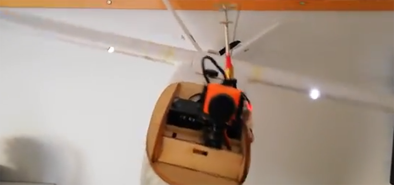
If you’re doing remote controlled flight, odds are you’re also flying FPV. Or you at least have a camera on board. If you’re transmitting to the ground, you may have noticed the antenna on your plane has some weird radiation patterns; bank your plane to the left or right, and your signal gets worse. [Ant0003] over on Thingiverse has a great solution to this problem that’s small, lightweight, and will fit into just about any airframe.
[Ant]’s flying a Mini Talon with FPV, and since planes turn slower than drones, and can fly much further than multicopters, the radiation pattern of the antenna is very important. In this case, [Ant] wants to keep the antenna perpendicular to the ground. This problem was solved with a cheap 9-gram servo and a few 3D printed parts that hold an SMA connector. One end of this wire goes to the video transmitter, and the antenna is screwed into the other end.
A servo alone does not make the antenna point straight up. To do this, [Ant] needed to program his flight controller. He’s using iNav, and a few clicks of the mouse makes one servo channel do whatever the gyroscope isn’t doing. The results (video below) speak for themselves. It’s an antenna that always points straight up, which is exactly what this video transmitter needed.


Very convoluted way of beating a weighted end and a pivot!
A weighted system would not work while inverted (Maverick) as it would hit the airframe unless it had 360° free rotation with no cables to get in the way (this system can keep it pointed down while inverted which acts the same while being right side up). It also has to deal with centripetal forces that could potentially force it to go to the horizontal like a centrifugal governor while in a flatspin or knife edge loops. The gyroscope is usually not affected by external forces, therefore it is used to keep a constant orientation.
The one thing that would help the system is if it had more freedom of rotation (than the ~180° it is getting now) or a second antenna mirroring it on the bottom.
And I feel like the 9g servo is probably lighter then the weight and will cope with any side wind loads better then the weight would. And probably reacts faster, too. And requires less room, since there is no need for a pendulum weight sticking out the bottom.
Not to mention that any mechanical system would need dampening.
All good points! No more posting while eating breakfast for me.
Dunning-Kreuger in full effect.
Stand back, I got this…
Airplanes generally coordinate turns so the lift vector is always along the X-Z plane of the aircraft (straight up left vs right). In full scale, it makes for a comfortable ride. Turning without smashing your passengers’ faces into the window or the fat guy next to them is a good thing it’s also much more efficient to turn in a coordinated turn than slipping around wings flat.
In most models, there is enough dihedral stability that they are fairly coordinated even if the dip on the end of the stick is a bank and yank neanderthal who’s rudder stick is as virgin as the turnsignal lever in a New York taxi cab.
So…now…care to guess why a weighted pendulum type stabilizer would be wholly inneffective? Same reason a gimbaled cup holder is a waste of money for a motorcycle.
Just ask Bob Hoover for a glass of tea if you don’t believe me.
Your comment is convoluted and wrong as well :D
so don’t come back please
I ABSOLUTELY LOVE YOUR STERN DIRECTNESS IN YOUR RESPONSE TO THAT HYPEREGOTIST WHOM SUFFERS FROM DELUSIONS OF GRANDEUR!!!!!
Perhaps I’m mistaken but I believe that is leaning out of the bank.
Shhh!
Don’t confuse him with facts.
Or you could design an antenna that has a better radiation patter for both the transmitter and the receiver. A variation on the cloverleaf antenna on the transmit side and something more directional on the receive side would work quite well. Using a circular polarized antenna has huge benefits with things that are moving or altering their orientation.
18dBi gain on a circular polarized antenna is going to give you great performance no matter what the orientation.
Antennas are a bit of black magic – especially if there are other elements in close proximity which can change the radiation pattern. They also tend to be rather expensive for good quality high gain ones. This is a pretty simple system to improve performance without much risk. I like it!
Aerospace antenna designer here. Boris’s suggestion is exactly what I would recommend to increase link margin. Going a little further I would use an antenna on the vehicle with a cardioid pattern facing downward. The cloverleaf antenna has more of a toroidal (donut) shaped pattern with the null facing downward. A CP patch on the underside would work best and be conformal to the structure. A cross dipole could also be used. Further, it may be better to increase the output of the transmitter, than use power on a stabilized servo system. Still, pretty cool to see a stabilized system like this.
This is actually a cleverly designed circular polarised antenna by Maarten Baert called the Pagoda. It’s got an axial ratio of ~1.3, so as you point out, the benefits of this tilting setup are not going to be very significant.
An antenna with 18dBi gain implies increased directionality, so actually orientation would then become critical. Unless you mean putting it on the ground station with either manual adjustment or an automated tracking system?
Is it not worth using 2 servos, so that the system can keep the antenna upright relative to pitch, as well as roll? seems to me that a loss of visual feedback when in a dive is less than ideal.
Depends on your planned flight behavior. Fixed wing aircraft probably wont be doing much acrobatic flight. Or at least not doing acrobatic flight when far enough away from the pilot to need the antenna gain.
Look I’ve got the answer for all this, it’s very simple.
If you’re having troubles with flight behavior you can contact me and I’ll give you a phone number to a aircraft discipline class where you can take your aircraft and you’ll be trained to listen to your command and US resolving any behavioral misconduct your aircraft might have. ????????
I have a feeling this is more of a “Can I do this” than a “Should I ACTUALLY do this” hack. Adding mass to an aircraft is RARELY a good thing.
It feels like those grams were mis-spent. And the added drag certainly isn’t helping either.
Other options I would have considered first…
1. Can I use an antenna with a better pattern? Even if I add the same mass, I don’t have to waste energy on the computations to keep one upright. I don’t have any extra moving parts. And I don’t have to account for any moving center of mass.
2. If I AM adding mass, Can I do it more efficiently?
2.a. Would adding the mass as batteries let me increase the transmit power to do the same job?
2.b. Would I be better off using multiple directional antennas? Perhaps thin copper foil “PCB” style antennas that run outward on each wing, and back along the fuselage? Bonus points for using software to determine the best direction to transmit, and using THAT antenna.
I was recently looking into whether any of the “antenna tracker” projects had ever been merged with the “camera gimbal” projects, such that you could put a truly-high-gain directional antenna on the model, and have it always point “home”.
It looks like not, and I don’t have the software chops to change that. Someone please make this a thing!
I did such a thing for my master thesis. I was using WiFi antennas and the hole system was mounted In a balloon, but still.. smells a bit like what you’re suggesting
There’s some abruptness to its movement at times. Any concern about Doppler or signal lock/tracking with that movement and these wavelengths?
2 antennas and beamforming could be a nice solution.
I and most of my friends fly free style or race drones so a low gain anntena works just fine for us. But i do think its a neat solution for long distance when using high gain anntenas.