We love electromagnetic displays: take the modern look of a digital readout, combine with the low-tech coil mechanism that you theoretically could create yourself, add a dash of random clacking sounds, and what’s not to like? Evidently, [Nicolas Kruse] shares our affection for these displays, because he’s taken it beyond theory and created a 7-segment magnetically-actuated display from scratch.
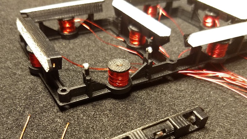
The display is 3D-printed, as you would expect these days. Each segment contains a small neodymium magnet, and each coil a 1 mm iron core for flux concentration. The coils are driven with a 1.6 A peak current, causing the segments to flip in less than 10 ms. [Nicolas] provides STL files for the display base, segments, and spools so you can print your own display. He’s also released the schematics and code for the driver, which uses an ATtiny44 to drive the coils through N- and P-channel MOSFETs. Initially designed to drive a passive 4×7 matrix of displays, the driver couldn’t quite manage to flip one segment without affecting its neighbors. However, for a single display, the driver works fine. We hope he figures out the matrix issue soon, because we really want to see a clock made with these displays.
You can see (and hear) a short video of the display in action after the break. The clacking does not disappoint!
We’ve featured projects using commercial flip displays on these pages before, as well as those using recycled flip-dot matrixes.


It is Very neat that the tiny magnets on the back hold the segments in position (with the iron core of the solenoid) when fully powered off.
I love this!
“the driver couldn’t quite manage to flip one segment without affecting its neighbors”
Maybe it’s because the magnets are at the middle.
There will be less influence if the magnets are on the tip of each segment:
( o = magnet)
-o—– -o—–
I o I o
I I I I
o I o I
—–o- —–o-
o I o I
I I I I
I o I o
-o—– -o—–
space formatting has failed…
using dots instead:
( “o” is magnet, “=” or “II” is segment)
.=o===……..=o===
II………o…..II………o
II………II…..II……….II
o……..II…..o……….II
.===o=……..===o=
o……..II…..o……….II
II………II…..II……….II
II………o…..II………o
.=o===……..=o===
Nice, but if I understand correctly your “drawing”, you are showing us two 7segment displays ? It would’ve been clearer if youd had only shown 1…And the technique doesn’t seem to work too well with adjacent units
you mean like that only with more complicated and at higher cost?
https://www.youtube.com/watch?v=XMqtcXTPZyI
You really opened us the eyes, thank you so much!
You are very much welcome!
in space for 8-segment (front) you have much more info available.
this has cards (with entire numbers or letters), not segments
This isn’t segmented displays. It’s flip-cards that rotate
That’s a splitflap display. Those have a defined set of characters printed on a wheel of flaps. The wheel is rotated to certain known positions to “drop” a certain amount of flaps in order to display a character.
With increasing size these things take longer to update, because in the worst case (you have a “B” but want an “A”) each characters display has to do a full rotation to get to the desired character.
One moving part + 3lines (digits+ all letters+ pictogram)
vs
7 moving parts + 7lines (digits+few letters)
It really depends on the requirements of the application, so neither setup is always the best choice. Just looking at number of moving parts and control lines and making a universal claim that one is better than the other ignores any other requirements which might be of a higher priority/critical to operation in a specific scenario. For example, a split flap is the clear choice for displaying many symbols/pictograms, but a seven segment display is the winner if you need to be able to update in less than a second (or have some strict requirements on power draw over a length of time). Additionally an extension of these 7 seg flip displays is flip dots that can be made into relatively high density graphical dot matrix displays which split flap technology is not capable of.
It’s a cool technology, but FYI don’t try to use it in a scrapyard. That big magnet they use to pick up cars causes it to act … erratically.
I seem to remember a version of this which used a bunch of ferrofluid sandwiched between glass to do this totally silently and with a certain organic fluidity added to the digital starkness of the seven-segment. which I thought was an interesting sort of duality. Super complex though.
Damn, E-ink on a budget…
Sounds easy to reproduce, i guess
Can this be combined with PCB coils to make simple-to-manufacture EM displays?
Judging from what Carl Bugeja did with PCB coils: Yes. Absolutely.
These look great, definitely want to make some of my own!
I suspect the problem with the matrix is that (unlike a LED matrix), the coils conduct in both directions, and so there are all sorts of alternate paths for current to flow through the surrounding coils. For this layout, where it looks like there’s heaps of space, I would fit each segment with separate set and reset coils, each with their own series diode to stop any crossfeeding/backfeeding. Twice as many coils to feed, but everything can be made the same polarity, so the driver circuit may actually be simpler.
I’m late at commenting on this. I don’t quite understand how the logic signals decide which mosfets to turn on but I see there some inverters that produce the gate voltage of the low side mosfets. A priori, this arrangement doesn’t guarantee that the upper side mosfet and the low side mosfet switch with a deadtime in between, this can cause shoot-through. Deadtime chips exist but it may be cheaper to have two separate coils for each segment wound in opposite directions in order to be able to feed them using voltage of the same sign while still causing flux in alternating directions in order to move the segments.