Here’s a neat trick for your next 3D-printer build or retrofit: a Z-axis sensor using a DIY strain gauge made from SMD resistors. We’re betting it could have plenty of other applications, too.
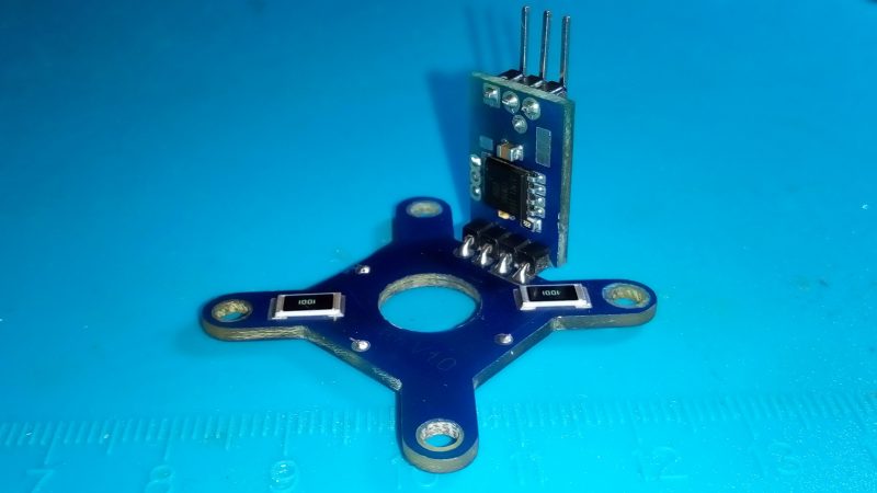
Conventional load cells, at least the ones you can pick up cheaply from the usual sources or harvest from old kitchen or bathroom scales, are usually way too big to be used on the extruder of a 3D-printer. [IvDm] wanted to build a touch sensor for his Hybercube printer, so he built his own load cell to do it. It consists of four 1000 ohm SMD resistors in the big 2512 device size. He mounted them to an X-shaped PCB and wired them in the classic Wheatstone bridge configuration, with two resistors on one side of the board and two on the other.
The extruder mounts into a hole in the center of the board and floats on it. Through an HX711 load cell driver chip, the bridge senses the slight flex of the board when the extruder bottoms out on the bed, and an ATtiny85 pulls a limit switch input to ground. [IvDm] even did some repeatability testing with this sensor and it turned out to be surprisingly consistent. The first minute or so of the video below shows it in action on the Hypercube.
We found the use of SMD resistors as strain gauges pretty clever here, but there’s plenty to do with off-the-shelf load cells: measuring how much filament is left on a roll, checking the thrust of a model rocket engine, or even figuring out if you’re peeing correctly.
Thanks to [jschoch] for the tip.


How does it work exactly? Has it got to do with the carbon inside?
This is really interesting.
Damn, this is unbelievably clever. I understand how it works, but it is one of those things that I’d probably dismiss as not really practical. I’m amazed it actually works.
If you understand how it works, why are you amazed it works?
It’s like the ether wind experiment, or the intricately chipped and hardened stone blades made by early humans. You know that it’s possible, but how well it works with so little is impressive.
Because although it coukd work, the desired effect is one of the criteria specifically designed out of resistors. They are supposed to be stable over temperature, age and mechanical stress. Changing their value with mechanical input is often called microphonics. I would bet, the cheaper the resistor, the greater the effect.
durfus mount (yes intentional) resistors are usually film based, so if you have a film (thin or thick) with a zig zag conductive pattern etched on it, compression or tension will change the length of said pattern and change the resistance
but only slightly .. it is measurable though
Osgeld,
The zig-zag pattern is not really relevant: it’s a method for impedance matching, with a side effect of introducing anisotropy. Good thing too. Most SMT resistors aren’t made that way anyway (except for some super-high-resistance ones).
Almost all SMD resistors – especially in the 1 kohm range, are metal film. But regardless, the way it works is that bending the resistor stretches the metal film, raising its resistance. Not by much, but enough to measure.
This is a clever design! I wonder if the designer has calibrated the output in volts/mm deflection to get some idea of sensitivity/repeatability or possible stress on the solder joints ?
One way to possibly get additional sensitivity from this design would be to rout a thin slot in the PCB directly underneath each resistor. The slots would slightly weaken that area of the PCB, concentrating the flexing there instead of distributing it across the entire arm. Worth a try at least.
*route*
Just drill a hole
Line of mouse bites?
“Rout” is correct. You rout a slot using a router. “Route” is a path.
No.
Rout – verb – to hollow out or cut a groove or pattern in a surface
Not only that, but none of the definitions for “route” include this.
Or you could use strain guages https://www.ebay.com/p/5pcs-Bf350-3aa-Bf350-350-Ohm-High-precision-Pressure-Resistance-Strain-Gauge-Set/769200641?iid=323087798934&chn=ps
They are even of similar size like the resistors.
I guess they should start making SMD strain gauges :-)
Sure, but these resistors cost less than 10 cents each. Even cheap strain gauges are around $1.
If something like this can be shown to be repeatable and robust enough for the given application, it’s pretty awesome.
They may be cheap, but they’re not going to be sensitive, due to the stiffness of the ceramic substrate.
Agreed. Clever “why didn’t I think of that” thing.
A quick review of the linked files didn’t reveal whether they used thin film or thick film resistors, but I’d guess thin film would work much better here (lower noise, better precision, lower tempco, metallic vs oxide resistive component).
But now that I think about it, why not just use a meandering copper trace on the PCB as the element? You can easily get 2 inches of trace in the space of a 2512 component, using 6 mil rules. Still pretty low resistance, but very low noise, and the mechanics aren’t confounded by the solder bond and the very stiff ceramic of the resistor.
With an appropriate (low-Z) amplifier I’ll bet the PCB trace would outperform the resistors for sensitivity vs. noise.
It’s been done, at least for Delta printers.
https://www.duet3d.com/DeltaSmartEffector
The designer even put the driver circuitry on the effector.
I haven’t seen a PCB trace variant for a cartesian printer, possibly just due to how variable the mounting styles are.
Somebody to order PCBs from JLCPCB for this? I would chip in for some – minimum order is 10pcs, I would opt for 2 :)
The really amazing thing is they make parts that are actually designed for this service called strain gauges. I suspect they are not as inexpensive as SMD resistors but for the most part, I like using parts that are designed to be used the way I am using them.
The first issue that comes along is mechanical creep in the solder joint, which is put under stress in this design. With a strain gauge, the gauge slip itself is flexible, it doesn’t carry mechanical forces – it merely deforms with the underlying material and it’s designed to do so in order to not interfere with the mechanism.
So the most likely failure after a number of load cycles is a) the solder joints start to conform to the load and the zero point of the bridge creeps out of alignment, b) the solder joints develop tin whiskers due to RoHS solder and mechanical strain, leading to short circuits eventually, c) the solder joints crack.
The points b and c are easily solved as long as you do not want to sell the device: Avoid the use of crappy (RoHS) solder. But I also prefer the use of proper components for a job, strain gauges in this case.
You certainly can do it using meandered traces on the PCB itself.
(But don’t you want to measure the extruder height without driving it into the bed?
I think capacitive or inductive sensing is better.)
I’ve often wondered why people don’t just make their beds conductive and use a pogo pin style probe. Effectively replace the sensor with a switch and do the measurement directly.
Here’s an example of a PCB-based load cell.
https://www.duet3d.com/DeltaSmartEffector
Thanks. Nice. My main concern is the space needed for this. Cca. 12cm² on the top and bottom layer. I wonder if this is useful without the opamp too.
It’s not like load cells and UV resin cost anything on Ali these days…
But yeah, this will work too I guess :-)
You could also just make a PCB with tiny wiggly lines and measure those.
Intresting, could also be used as a simple cnc touch probe…