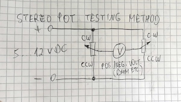
Sometimes the simplest hacks can be the most useful or ingenious, and such is the case with [Keri Szafir]’s method of ensuring that potentiometers used in audio devices are matched. If you consider a typical stereo amplifier for a moment, you’ll see two amplifiers in one box with a single volume control. Two channels, one knob? Volume knobs are ganged stereo potentiometers.
All potentiometers are not created equal, and particularly in the cheaper devices they may not have a consistently matched resistance across both pots and across their travel. This messes up the stereo balance, so naturally it’s worth selecting a part with good matching. [Keri] selects them not with his golden ears, but by wiring both pots together as a Wheatstone bridge. A meter between the two wipers would detect any current due to a mismatch.
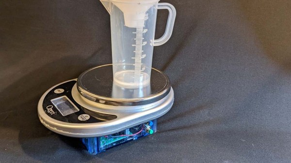
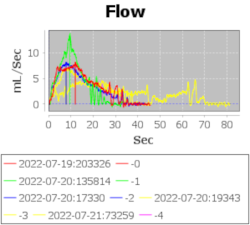
If you’re dealing with a chronic illness, the ability to continuously monitor your symptoms is indispensable, helping you gain valuable insights into what makes your body tick – or, rather, mis-tick. However, for many illnesses, you need specialized equipment to monitor them, and it tends to be that you can only visit your doctor every so often. Thankfully, we hackers can figure out ways to monitor our conditions on our own. With a condition called BPH (Benign Prostate Hyperplasia), one of the ways to monitor it is taking measurements of urinary flow rate. Being able to take these measurements at home provides better insights, and, having found flow rate measurement devices to be prohibitively expensive to even rent, [Jerry Smith] set out to build his own.
This build is truly designed to be reproducible for anyone who needs such a device. Jerry has intricately documented the project and its inner workings – the 31-page document contains full build instructions, BOM for ordering, PCB description and pinout diagrams, calibration and validation instructions, and even software flowcharts; the GitHub repo has everything else you might need. We’re pleasantly surprised – this amount of documentation isn’t typically seen in hacker projects, and is even more valuable considering that this is a medical device that other hackers in need will want to reproduce.
For the hardware, [Jerry] took a small digital scale of a certain model and reused its load cell-based weighing mechanism using an HX711 amplifier, replacing the screen and adding an extra box for control electronics. With an Arduino MKR1010 as brains of the operation, the hardware’s there to log flow data, initially recorded onto the SD card, with WiFi connectivity to transfer the data to a computer for plotting; a DS3234 RTC breakout helps keep track of the time, and a custom PCB ties all of these together. All of these things are easy to put together, in no small part due to the extensive instructions provided.
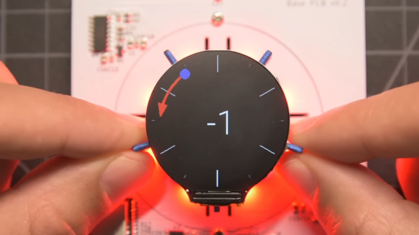
At Hackaday, we love those times when we get a chance to follow up on a project that we’ve already featured. Generally, it’s because the project has advanced in some significant way, which is always great to see. Sometimes, though, new details on the original project are available, and that’s where we find ourselves with [Scott Bez] and his haptic smart knob project.
Alert readers may recall [Scott]’s announcement of this project back in March. It made quite a splash, with favorable comments and a general “Why didn’t I think of that?” vibe. And with good reason; the build quality is excellent, and the idea is simple yet powerful. By attaching a knob to the shaft of a brushless DC motor and mounting a small circular LCD screen in the middle, [Scott] came up with an input device that could be reprogrammed on the fly. The BLDC can provide virtual detents at any interval while generating haptic feedback for button pushes, and the LCD screen can provide user feedback.
But how is such a thing built? That’s the subject of the current video, which has a ton of neat design details and build insights. The big challenge for [Scott] was supporting the LCD screen in the middle of the knob while still allowing the knob — and the motor — to rotate. Part of the solution was, sadly, a hollow-shaft motor that was out of stock soon after he released this project; hopefully a suitable replacement will be available soon. Another neat feature is the way [Scott] built tiny strain gauges into the PCB itself, which pick up the knob presses that act as an input button. We also found the way button press haptics are provided by a quick jerk of the motor shaft very clever.
This is one of those projects that seems like a solution waiting for a problem, and something that you’d build just for the coolness factor. Hats off to [Scott] for following up a sweet build with equally juicy details.
We are always impressed with something so simple can actually be so complex. For example, what would you think goes into an analog computer? Of course, a “real” analog computer has opamps that can do logarithms, square roots, multiply, and divide. But would it surprise you that you can make an analog device like a slide rule using a Wheatstone bridge — essentially two voltage dividers. You don’t even need any active devices at all. It is an old idea and one that used to show up in electronic magazines now and again. I’ll show you how they work and simulate the device so you don’t have to build it unless you just want to.
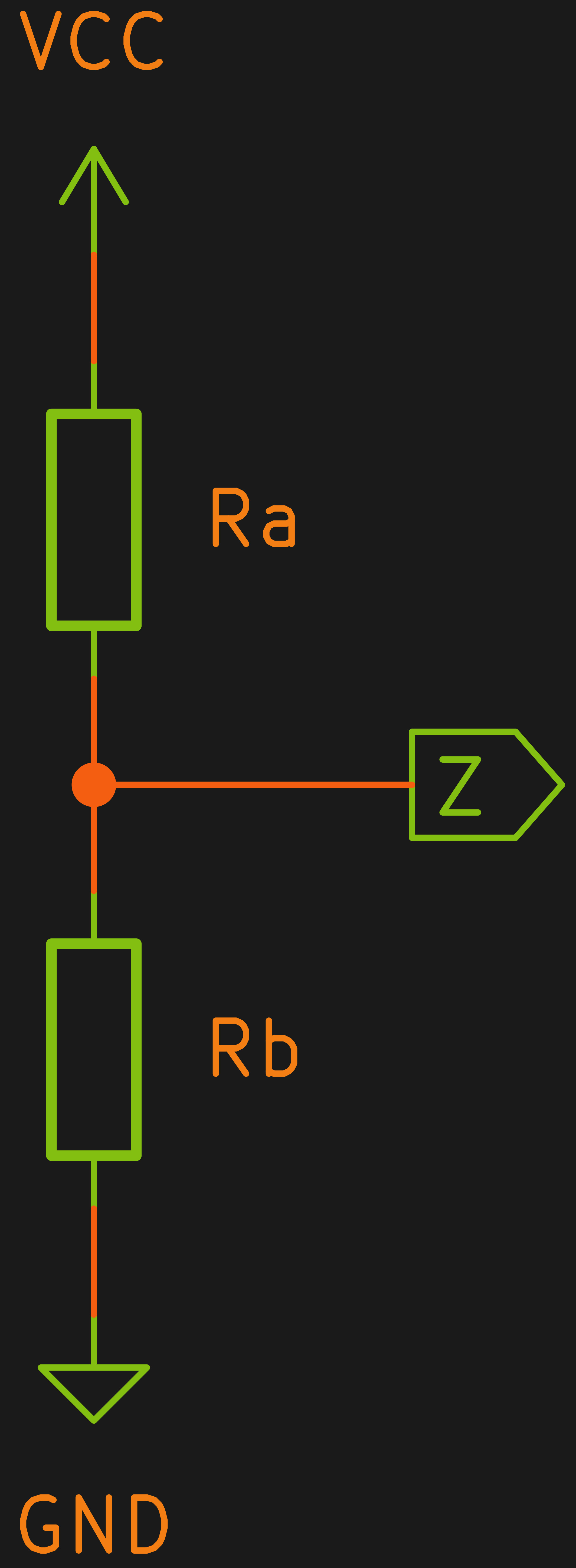
A voltage divider is one of the easiest circuits in the world to analyze. Consider two resistors Ra and Rb in series. Voltage comes in at the top of Ra and the bottom of Rb is grounded. The node connecting Ra and Rb — let’s call it Z — is what we’ll consider the output.
Let’s say we have a 10 V battery feeding A and a perfect voltmeter that doesn’t load the circuit connected to Z. By Kirchoff’s current law we know the current through Ra and Rb must be the same. After all, there’s nowhere else for it to go. We also know the voltage drop across Ra plus the voltage drop across Rb must equal to 10 V. Kirchoff, conservation of energy, whatever you want to call it. Let’s call these quantities I, Va, and Vb. Continue reading “Circuit VR: The Wheatstone Bridge Analog Computer”→
Sometimes you just get lucky. I had a project on my list for a long time, and it was one that I had been putting off for a few months now because I loathed one part of what it entailed — sensitive, high-accuracy analog measurement. And then, out of the blue I stumbled on exactly the right trick, and my problems vanished in thin air. Thanks, Internet of Hackers!
The project in question is a low-vacuum regulator for “bagging” fiberglass layups. What I needed was some way to read a pressure sensor and turn on and off a vacuum pump accordingly. The industry-standard vacuum gauges are neat devices, essentially a tiny little strain gauge on a membrane between the vacuum side and the atmosphere side, in a package the size of a dime. (That it’s a strain gauge is foreshadowing, but I didn’t know that at the time.) I bought one for $15 ages ago, and it sat on my desk, awaiting its analog circuitry.
See, the MPX2100 runs on 12 V and puts out a signal around 40 mV on top of a 6 V offset. That voltage level is inconvenient for modern 3.3 V microcontroller ADCs, and the resolution would get clobbered by the 6 V signal if I just put a voltage divider on it. This meant whipping together some kind of instrument amplifier circuit to null out the 6 V and amplify the 40 mV for the ADC. The circuits I found online all called for 1% resistors in values I didn’t have, and mildly special op-amps. No fun, for me at least. So there it sat.
Cut the blue wire or the red wire? HX711 module and pressure sensor on the left.
Until I ran into this project that machetes through the analog jungle with one part, and it happened to be one I had on hand. A vacuum pressure sensor is a strain gauge, set up like a Wheatstone bridge, just like you would use for weighing something with a load cell. The solution? A load-cell ADC chip, the HX711, found in every cheap scale or online for under a buck. The only other trick was finding a low-voltage pressure sensor to work with it, but that turns out to be easy as well, and I had one delivered in two days.
In all, this project took months of foot-dragging, but only a few clicks and five minutes of soldering once I got the right idea. The industrial applications and manufacturers’ app notes all make sense if you are making hundreds or millions of these devices, where the one-time cost of prototyping up the hard bits gets amortized, but the hacker solution of using a weight-scale chip was just the ticket for a one-off. That just goes to show how useful sharing our tips and tricks can be — you won’t get this from the industry. So send us your success stories, and your useful failures too, and Read More Hackaday!
This article is part of the Hackaday.com newsletter, delivered every seven days for each of the last 200+ weeks. It also includes our favorite articles from the last seven days that you can see on the web version of the newsletter.
Want this type of article to hit your inbox every Friday morning? You should sign up!
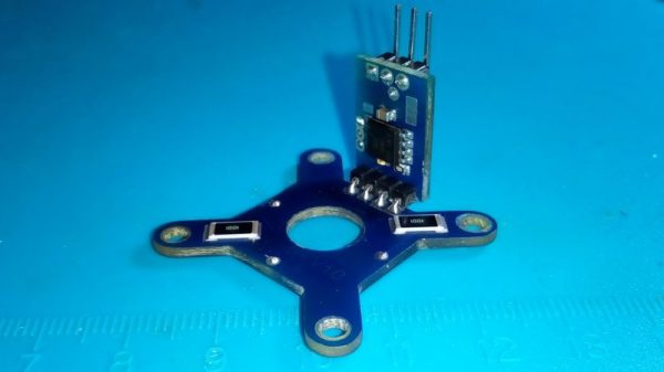
Conventional load cells, at least the ones you can pick up cheaply from the usual sources or harvest from old kitchen or bathroom scales, are usually way too big to be used on the extruder of a 3D-printer. [IvDm] wanted to build a touch sensor for his Hybercube printer, so he built his own load cell to do it. It consists of four 1000 ohm SMD resistors in the big 2512 device size. He mounted them to an X-shaped PCB and wired them in the classic Wheatstone bridge configuration, with two resistors on one side of the board and two on the other.
The extruder mounts into a hole in the center of the board and floats on it. Through an HX711 load cell driver chip, the bridge senses the slight flex of the board when the extruder bottoms out on the bed, and an ATtiny85 pulls a limit switch input to ground. [IvDm] even did some repeatability testing with this sensor and it turned out to be surprisingly consistent. The first minute or so of the video below shows it in action on the Hypercube.
Temperature is one of the most frequently measured physical quantities, and features prominently in many of our projects, from weather stations to 3D printers. Most commonly we’ll see thermistors, thermocouples, infrared sensors, or a dedicated IC used to measure temperature. It’s even possible to use only an ordinary diode, leading to some interesting techniques.
Often we only need to know the temperature within a degree Celsius or two, and any of these tools are fine. Until fairly recently, when we needed to know the temperature precisely, reliably, and over a wide range we used mercury thermometers. The devices themselves were marvels of instrumentation, but mercury is a hazardous substance, and since 2011 NIST will no longer calibrate mercury thermometers.
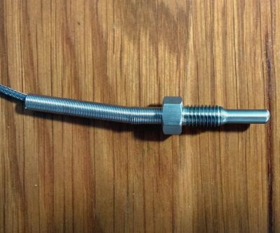
A typical Pt100 RTD probe
Luckily, resistance temperature detectors (RTDs) are an excellent alternative. These usually consist of very thin wires of pure platinum, and are identified by their resistance at 0 °C. For example, a Pt100 RTD has a resistance of 100 Ω at 0 °C.
An accuracy of +/- 0.15 °C at 0 °C is typical, but accuracies down to +/- 0.03 °C are available. The functional temperature range is typically quite high, with -70 °C to 200 °C being common, with some specialized probes working well over 900 °C.
It’s not uncommon for the lead wires on these probes to be a meter or more in length, and this can be a significant source of error. To account for this, you will see that RTD probes are sold in two, three, and four wire configurations. Two-wire configurations do not account for lead wire resistance, three-wire probes account for lead resistance but assume all lead wires have the same resistance, and four-wire configurations are most effective at eliminating this error.
 For the hardware, [Jerry] took a small digital scale of a certain model and reused its load cell-based weighing mechanism using an HX711 amplifier, replacing the screen and adding an extra box for control electronics. With an Arduino MKR1010 as brains of the operation, the hardware’s there to log flow data, initially recorded onto the SD card, with WiFi connectivity to transfer the data to a computer for plotting; a DS3234 RTC breakout helps keep track of the time, and a custom PCB ties all of these together. All of these things are easy to put together, in no small part due to the extensive instructions provided.