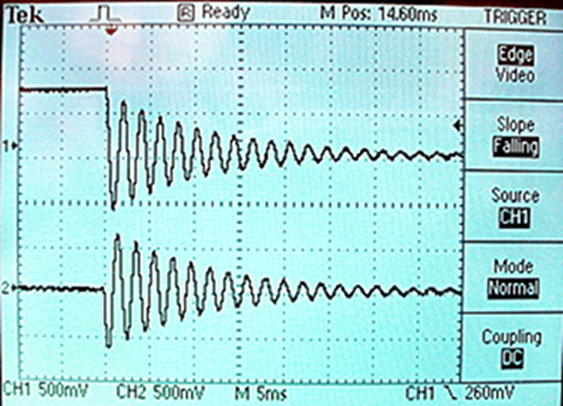
When you think of analog computing, it’s possible you don’t typically think of FPGAs. Sure, a few FPGAs will have specialized analog blocks, but usually they are digital devices. [Bruce Land] — a name well-known to Hackaday — has a post about building a digital differential analyzer using an FPGA and it is essentially an analog computer simulated on the digital fabric of an FPGA.
Whereas traditional analog computers use operational amplifiers to do mathematical integration, on the FPGA [Land] uses digital summers The devices simulate a system of differential equations, which can be nonlinear.
Of course, at heart it is still a digital device in which an 18-bit number format represents quantities. Although theoretically capable of infinite resolution, a real analog system will have some limit based on the noise floor, component variations and measurement uncertainty, so in practice 18 bits is good enough for most purposes. However, [Land] also extends to 27 bits for those applications that need better accuracy. Analog devices are, of course, inherently parallel in the same manner as FPGAs, so that part matches up well.
The example code is in Verilog and there’s even a case where a CPU cooperates with the (simulated) analog computer. At one time, it wasn’t clear that analog computers wouldn’t take over the world. They even made portable ones — if you consider 28 pounds portable. We’ve recently seen a few posts about analog computers. Maybe they’ll make a comeback.


I love the idea, and the writeup is suburb as is the code provided. My favorite part of it all however is the no-nonsense website, which reminds me of the better days if the internet back when I was still in school…
And, also, the straightforward, logical description that follows from someone properly knowing what they’re talking about. It’s rare a project writeup feels so reproducible!
But … where do I plug the wires? I like the idea of digital op-amps and integrators and such, but once I’m having to reduce a system to code, I might as well run it through Matlab/Simulink or Spice, or something. No, what I want is something with banana jacks, or something similarly easy, like RJ11s or 3-pin headers. I don’t care if the 10-turn pots are actually digital encoders with integrated LED readouts. It would be fun to have something that acted mostly like an old school analog computer, where “mostly” means everything but the drift, offset, and noise. I’m thinking that ATtinyxx might make great individual modules. Or bigger AVRs for modules needing more I/O, such as the aforementioned digital pot, or a graphic LCD “plotter”.
This is normal digital signal processing on a discrete-time (clocked) FPGA. There are more creative approaches that use an FPGA in continuous time (asynchronous). Because an FPGA still only contains switches (on/off) the signals must be binary. But analog information can be encoded in the (continuous) time between pulses.
The only paper I’ve seen on this topic that actually does the real computation in the continuous time domain in a rigorous way is https://dspace.mit.edu/bitstream/handle/1721.1/78468/834089219-MIT.pdf
DDAs do not traditionally leverage “normal” DSP techniques. It is essentially a digital analogue computer, if that makes sense. By analogue, I do not mean analog as in a continuous signal. I like to spell it analogue to remind me that these computers simply form an analogue to some type of system to be modeled. In fact, analogue computers need not be electronic at all; the slide ruler is a somewhat modern example. Of course the op amp was the workhorse of electronic analogue computers. Op amp circuits provided basic math functions, and could be chained together to simulate physical systems described by differential equations. The DDA uses digital building blocks in place of op amp circuits to perform simulations. This opens up some really cool possibilities, most likely as some type of digital accelerator.
Why not use a FPAA they cost about $15? Well other than the learning benefit obviously.