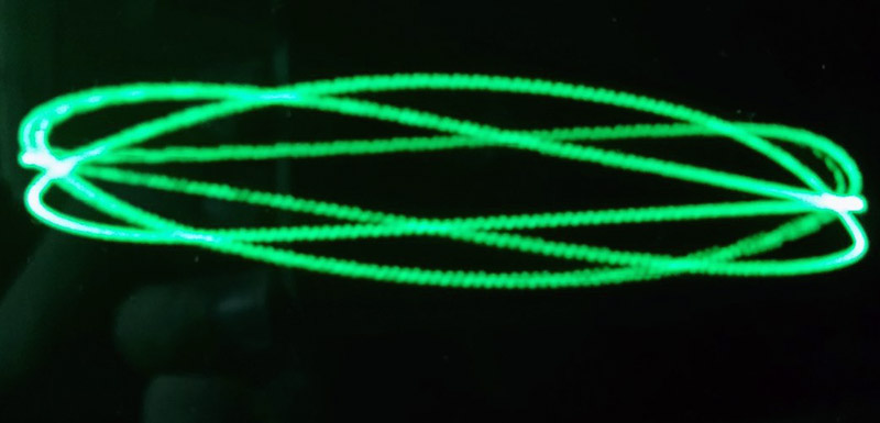
A Lissajous curve is formed when two sine waves plotted on their respective X and Y axes. You can see one using an oscilloscope and a couple of signal generators, if you play with one of those ‘pendulums tracing in the sand’ toys, or if you really need something sciencey for your home decor you can trace them out with a disassembled CRT. That’s what [Emily] did with the LissaJukebox. It traces curves. No, it’s not a curve tracer, that’s another tool altogether
If you’re going to put squigglies on a CRT, you obviously need a CRT, and it needs to look good. There are a few options out there, from old oscilloscope tubes, the CRTs found in old VHS camcorders, to tiny electrostatic tubes that are slightly easier to drive. For this build, [Emily] chose an old, bog-standard, black and white television. But the screen is green, right? Yeah, but if you carefully mask off a CRT and buy some stained glass spray paint, a CRT can be any color you want. Except for purple, the purple stained glass spray paint didn’t work for some reason.
To generate the various functions, [Emily] used an XR2206 function generator, sold in kit form on Amazon, eBay, and various other online retailers for a pittance. One of these function generators controls the X axis, another the Y, and both of these generators are fed into a 15 Watt stereo amplifier board to run the deflection coils in the CRT. If you’re following along at home, yes, this is dangerous. Don’t touch the CRT or it will stop your heart. Those of us whose hearts are as black as coal are safe.
There were a few modifications needed to turn the XR2206 function generator ‘kit’ into something a bit more useful for this project. The through-hole pots were replaced with panel-mount pots, and the range/amplitude setting is now controlled with a rotary switch.
Is it useful? Well, actually, if you’re building a set for a TV show and you need something that looks ‘sciencey’, a LissaJukebox should be right up your alley. Other than that it looks pretty, and we now know there’s a spray paint that will turn your old, boring black and white CRT into a glorious amber phosphor. Can’t beat that.


We control the horizontal, we control the vertical, etc, etc, etc.
Wow…great call back!
My dad and I used to laugh about that back when I was little.
I wonder how many people know what we are talking about?
It took the best part of a minute to find and watch it on YouTube…
Reminds me of the Marantz 4400
Brilliant! The green tint is the shizzz.
Heh. I remember being able to buy “green screen” kits in the early home computer days. A sheet of clingy green plastic that you just cut to size for your TV…
An alumni of doing this in 1970 in HS. You can use the TV’s vertical as horizontal and make a normal timebase good for bass-mid range. You can get colored plastic sheeting on a roll at hobby stores. It’s coming up to Easter, decorating baskets etc.
I picked up an old analog medical scope with DC response and nanovolt sensitivity, with a white long persistence phosphor portable TV style tube. Would Holey-wood have it green?
Remote control lexan body paint is translucent (excluding the metallics). We used to use those maybe 20 years ago to put custom tints on car lights (yellow, amber, red, etc). Heat and fuel resistant too.
You want purple? Or pretty much any colour you can think of? I use Lee gels for this: http://www.leefilters.com/lighting/colour-list.html Available at any DJ or theatre house, or PA rental agency, or B&H, or even Amazon. Lee offers a handy little booklet containing samples of most of their gels, available for free or really cheap from most places. Very helpful.
Side notes on the Lissajous.
The Lissajous has a long history as a test tool in the early days of o’scopes. I actually had to learn how to use it to measure frequency in my first Jr, High school electronics class.
Frequency standards were hard to come by and not tunable. A Lissajous signal can show the exact multiple of two frequencies. Forget frequency counters, they cost as much as a car in the early days.
If you look up the “octopus” at ARRL’s site you will find a way to use it as a troubleshooting tool.
And …
In the article picture you can use the image to work out the SMPSU switching frequency.
I’ve seen a lot of projects using camera viewfinder CRTs over the years to get me interested in procuring one myself (a nice big JVC studio camera one). And then I found this Youtube video (https://youtu.be/1VUGmJgzCfQ) (@ 18:00) .
So, there are a couple important takeaways from that part of his video. 1. The viewfinders in those broadcast cameras were being much harder than they might have otherwise been. More kV = more chance of X-rays. A viewfinder from a thrift-store camcorder won’t be driven that hard. 2. The guys who got cancer spent a lot of time with CRTs right next to their heads.
You won’t get cancer from playing with a viewfinder. Chances are much higher that one might accidentally shock themselves. Check out Fran Blanche’s video on whether oscilloscope CRTs emit X-rays.
Random: you can still get “flat” CRTs. They can be driven using a relatively simple piezotransformer based driver and even run directly from a 2 stage doubler off a standard el cheapo CCFL inverter board. Old case mods with burned out tubes are a good source but connect a 39K resistor from -HV to Gnd for safety! Bit of Arduino with the curves preprogrammed and voila.
You can even make a bad copy of the old Tek colour CRT using an old picture frame or phone LCD panel spaced about 0.3″ away with its backlight + reflector film taken outand programmed with the appropriate sequencing though might be a tad grainy.
Note that the yoke would need modification as it wasn’t designed to scan this quickly.
De-coding what you said.
Where do I source these flat CRTs? Do you mean literally flat, like in their shape, or is it their behavior you refer to?
What is a 2 stage doubler? Do you connect one of these to a Cold Cathode F something L something inverter board typically found in discarded gamer PCs?
But let the HV slowly bleed to ground via a 39K resistor do reduce chance of untimely death?
Then you lost me completely … drive LCD panels using CRT stuff?
Hmm. A CRT isn’t going to work very well with -HV on the screen, reverse-biased like that.
I’d love to see a 39K resistor on a typical CRT HV supply. Even with a 1 kV CCFL supply it’s going to be a 25 watt heater, assuming the inverter doesn’t promptly shut down or let all its smoke out. With the 10 kV used on a typical monochrome CT, it would be nice and bright. For a little while anyway.
If you’re going to go through the trouble of driving all those colored pixels on a LCD to simulate a programmable color filter, you could be really cool and take it to the next level, and program those pixels to make an image! You could even use that handy CRT behind it as a backlight!