
Knowing in what absolute direction your robot is pointed can be crucial, and expensive systems like those used by NASA on Mars are capable of calculating this six-dimensional heading vector to within around one degree RMS, but they are fairly expensive. If you want similar accuracy on a hacker budget, this paper shows you how to do it using cheap MEMS sensors, an off-the-shelf motion co-processor IC, and the right calibration method.
The latest article to be published in our own peer-reviewed Hackaday Journal is Limits of Absolute Heading Accuracy Using Inexpensive MEMS Sensors (PDF). In this paper, Gregory Tomasch and Kris Winer take a close look at the heading accuracy that can be obtained using several algorithms coupled with two different MEMS sensor sets. Their work shows that when properly used, inexpensive sensors can produce results on par with much more costly systems. This is a great paper that illustrates the practical contributions our community can make to technology, and we’re proud to publish it in the Journal.
Micro-electro-mechanical systems (MEMS) sensors have been around for over a quarter of a century, but in recent years, their adoption has grown exponentially. Several categories of modern devices would be radically different, if not impossible, without MEMS sensors: robots, drones and autonomous vehicles all use these devices to estimate which way and how fast they’re travelling. They’re also probably in your phone. Compared to larger and more expensive sensors, the small, inexpensive variety are usually thought of as inherently less accurate. This paper proves that this is not necessarily the case: properly calibrated sensors coupled with the right algorithm can produce heading errors of one degree RMS.
The authors test two sensor sets: Invensense’s MPU9250 and ST Microelectronics’ LSM6DSM/LIS2MDL, both of which combine accelerometers, gyroscopes, and magnetometers. They paired each set with EM Microelectronic’s EM7180 motion co-processor. The co-processor performs a proprietary sensor fusion algorithm, but also passes through the raw sensor data so that other algorithms can be tested in an apples-to-apples manner. As well as the built-in algorithm, they applied the open-source Madgwick algorithm and their own proprietary method. They tested the algorithms both with and without prior sensor calibration to determine how much this would improve the results.
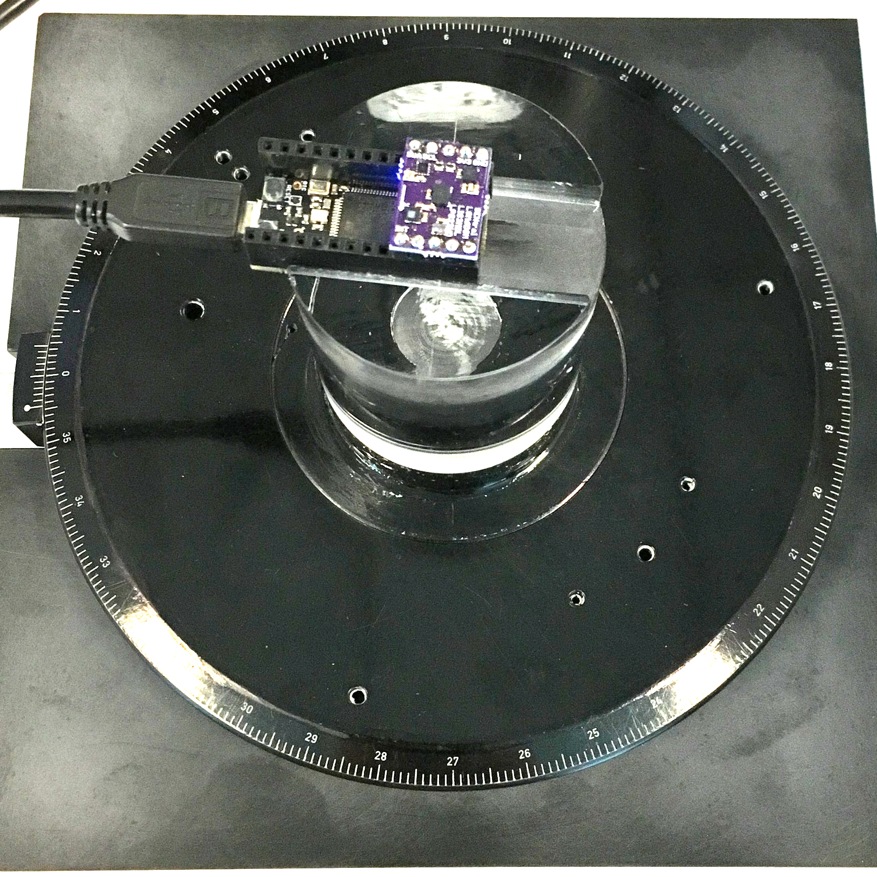
To test the various combinations, the authors sourced a used Zeiss rotary stage from Ebay. Using an acrylic spacer to isolate the sensors from any influence of the metal parts, they mounted each sensor package on the stage in turn. The stage can be adjusted to a resolution of a tenth of a degree, providing an ideal testbed for evaluating heading accuracy.
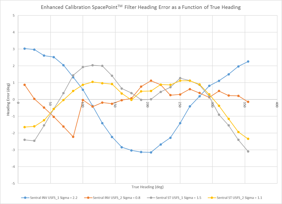 After analyzing all the data, the authors determined that the proprietary solutions can produce an RMS heading error up to around twice as good as the open-source algorithm. However, the big surprise is the impact of calibration. Their extended pre-calibration routine brought even the worst, fifteen-degree setup, in line with the best.
Tantalizingly, there is still a predictable sinusoidal component to the error, which might be a result of magnetometer/accelerometer misalignment, that could stand to knock the error in half if that can be removed.
We applaud the empirical approach the authors took with this paper; their methodical assessment of sensor accuracy is exactly the kind of thing we are looking for in the Journal.
We Want Your Submissions
The Hackaday Journal (full title: the Hackaday Journal of What You Don’t know) is now – and continuously – accepting submissions for publication. You don’t have to submit the full paper right away if you just want to get some feedback on the topic; submitting a brief summary or abstract is fine. We know you have ideas we’d all benefit from reading about, and we want you to share them. So, drop us a line with your awesome paper topic.


I’d like to see more people experiment with “virtual” sensors comprised of multiple accelerometers, gyros and fusion techniques to increase the accuracy above what the individual sensors could achieve on their own. I have seen a little bit of research on the subject, but I don’t think it has gotten the attention it deserves especially when we consider that the low cost of individual sensors could make such a configuration still be cost effective even for cost conscious hobbyists and consumers.
@msat: would like to see this as well. Can you please provide some links as to what you’ve found so far? I’m developing a specialized field tool, centered around U-Blox’ ZED-F9P RTK GNSS module. So, the precise positioning part is covered. But what about heading, etc? This article was very helpful regarding calibration of commodity MEMS sensors, but using multiple sensors may help a great deal.
I recommend to look on the Kris Winer github, lot of useful informations and codes :)
https://github.com/kriswiner
Jarad, it has been several years since I looked into this, but doing a quick search brought up this paper which I believe was the one I saw back then:
https://pdfs.semanticscholar.org/cabe/436d6852ea72e21c436e5c1df9cf4c74196b.pdf
“6. Conclusions
In this paper, the dynamic performance of the KF was analyzed to improve the accuracy of a MEMS
gyroscope by combining the multiple measurements of a gyroscopes array. Six MEMS gyroscopes with
the same specification were used to construct a virtual system. It displayed a 1σ noise of 0.2°/s for the
combined rate signal in the constant rate test, which reduced the noise by a factor of more than eight
compared to the single gyroscope in the array. It also showed that the combined rate signal could
reproduce the dynamic characteristic of the input rate signal in the dynamic condition.”
I don’t have access to the following paper, but it looks relevant.
https://ieeexplore.ieee.org/abstract/document/7995643
If you do some searching on the subject there might be some additional research on the topic.
I’m not smart enough for all that math stuff required to implement my own, so hopefully one day someone will release an off the shelf unit for those of us who are interested to play with.
One last thing: I’ve heard that mems devices eventually get out of calibration, though I’m not certain why. If the calibration procedure is complicated, that might pose a problem for hardware out in the field.
That’s great info, thank you!
I’m not well-practiced with interpreting the various mathematical representations made in your given scholarly article; I think in code, thus why I was trying to find someone that did it. A cursory search turned up a multitude of articles for this approach. This is the one I’m reading currently:
https://insidegnss.com/wp-content/uploads/2018/01/2012-sepoct-Roth.pdf
Openshoe.org does this with a lot of cheap IMUs on the same PCB. They have a bunch of articles linked on how to fuse the IMU data, evaluations etc. They also have KiCad files for a 32 IMU board.
This already exists. Just make a model of the sensors and their placements. And from the model, you can implement a a Kalman filter. I’m not sure how much better the ‘virtual’ sensor will be. You can use it to estimate poses of humans by strapping sensors. I think one sensor would be good enough. Usually a good calibration is what increases accuracy the most.
“To test the various combinations, the authors sourced a used Zeiss rotary stage from Ebay.”
So, they developed a device that if properly hidden on the dial of a safe/money vault, it will record the combination when the safe is opened,..
I like the way you think!
But in the spirit of the 555 timer, you could do that with just an accelerometer — you only need to know where gravity is when the wheel is stopped. The gyro will make the math easier. You certainly don’t need to know which way north is.
But back on topic… it’s like a skimmer, but for bank vaults. Hmm…
I’m curious about the limits and stability of this method. Is the sensor stable over a range of temperatures, pressures, maybe gas concentrations (thinking about the MEMS oscillator and helium issue a little while back), over time, etc?
The environmental issues seem solvable based on the work done for high altitude balloons. The time factor would be a bigger challenge if the sensor changes in some way over time and needs to be re-calibrated relatively frequently.
Instead of now obsolete MPU-9250, which belongs to the family of most popular IMUs for quad-copter flight-controller boards (6-axis MPU-6050 and MPU-6500). It would be more interesting to see the ST products comparison with newer ICM-20948
My read of the article is that the calibration routine makes a lot more difference than the choice of device. They get the “bad” IMU down to 2%ish after sensor pre-calibration, which is competetive with the “good” ones.
I’m still super-interested in the ability of open-source sensor fusion routines, though. And would love to see the sensors tested out in more dimensions too. There’s a lot more to do here. Hope this sparks some fires.
I absolutely agree with what you are saying. But new(er) IMU design might suggest better internals in terms of noise characteristics (SNR, etc). However, after quick glance into datasheet, it seems that TDK/Invensense mostly focused on power consumption optimization.
I am in progress of prototyping a thing which will use ICM-20948 (at the moment struggling to dial my photoresist exposure/etching process to get good quality 0.2/0.2 mm traces/gaps required for IMU package…Yeah, I’ve herd about OSHPark/PCBNew/etc and use them occasionally when it gets to complex designs. But this is for evaluation of couple components working together, not too complex, that is why I don’t want to wait for a number of weeks for delivery).
So, I am about to evaluate internal digital motion processor (DMP) of the ICM-20948 agains popular motion fusion algorithms (Mahony/Madgwick). The major difference from older MPU-9250 is that its DMP can do motion-fusion by 6-axis only (acc + gyro). While raw magnetometer data you had to mix-in by yourself in the host-controller code.
The DMP of ICM-20948 does motion fusion by all 9-axes (acc + gyro + mag). Similar to what does the reviewed “more expensive solution” from PNI Corp (propitiatory code and EM7180 dedicated motion co-processor/sensor-hub chip). So it would be interesting to see the comparison between mentioned popular fusion algorithms (Mahony/Madgwick) and DMP of the ICM-20948., just as they did it with PNIs product.
We have done some qualitative testing with the ICM20948 using its DMP and this solution does work very well. No quantitative comparisons yet.
We don’t plan to use the ICM20948 simply because it requires a two power-rail solution, and for small boards this is a complication not worth the trouble when as good or better results cam be achieved with other sensor suites.
Thank you Kris,
Yes, that is the major issue working with it. Makes it harder to fit with popular development boards working at 3.3V or 5V. However if the host controller is powered at 1.8V (not my case) the whole ICM20948 can work from the same 1.8V power source as well (VDDIO is required to be 1.8V, while VDD can be either 1.8V or 3.3V).
Arduino code or it didn’t happen.
The trouble with such a heavy reliance of a pre-calibration is that it only works there in that spot – where you made the calibration. If you move around in a real-world environment, you are experiencing an always-changing magnetic field. Metal objects present in an enclosure can cause a different calibration for an IMU board inside it. So, some magnetometers store an internal sphere of nominal readings (in 3d polar coordinates), which is used to “always be calibrating all the time”.
My thought is that if these two solutions are compared in the real world, they would be much more comparable.
That first PDF link kicks off my virus scanner. Someone might want to check into that.
Dear HaD,
Please DO NOT use Google Drive to distribute documents. There are two reasons: (1) Google is inherently EVIL. Stay away from them. (2) Google Drive is BROKEN. For example I could not download your .pdf (see the results below). However, I found using the Print option and preventing the .pdf document from opening in my browser settings allowed me to save the .pdf,, albeit under a strange Google job name (which was easily renamed).
Attempting to download the document from Google Drive produces these results (I am using the latest mainstream release of the 64-bit Firefox browser):
“Google Drive can’t scan this file for viruses. We are experiencing technical difficulties. Would you still like to download this file? Hackaday_Journal-GregoryTomasch_KrisWiner-Heading_Accuracy_Using_Mems_Sensors.pdf (1.6M)”
Enabling the download results in this message (likely from the browser):
“File not found
An error occurred during a connection to doc-0s-1c-docs.googleusercontent.com.
* Check the file name for capitalization or other typing errors.
* Check to see if the file was moved, renamed or deleted.”
This is the broken link that produced the error above:
https://doc-0s-1c-docs.googleusercontent.com/docs/securesc/ha0ro937gcuc7l7deffksulhg5h7mbp1/7r1brmehbig9fhb3ibsp4miifbejoap1/1552449600000/12625438373084340985/*/1FaUtM_IqvkPp8U9fE1eF8rrjwmW1U5an?e=download
There you go!
@Elliot Williams
We are already working on our next installment. We have a 1.5-axis stage built and we are planning additional measurements to test the effect of pitch and roll (to +/- 20 degree IIRC) on heading as well as testing the statistical distribution of results using many more sensor breakout boards.
I suspect that if GNSS aiding is used as an input to an appropriate Kalman filter, that the azimuth accuracy could be significantly improved. The filter would in effect estimate the misalignment between the acceleration deduced from GNSS velocity measurements and the acceleration seen from the accelerometers in the IMU. The disadvantage is that this only works when there is occasional acceleration, and does not help in the static case. There, a GNSS compass (two antennas and phase comparison) could provide using static heading aiding. (Does anyone know an inexpensive source of a GNSS compass module?) I think that the issues that have been mentioned here regarding challenges with reliably measuring the magnetic field make it less useful than GNSS aiding, and in many applications only practical as a backup in case GNSS is not available.
Huh. I wasn’t aware one could use GNSS to derive a static heading. Are you aware of any open source software implementations that could do this? I have some GNSS modules that should meet the requirements and am interested to try.
Huh. I didn’t know you could do such a thing. I might have some GNSS modules that would suit this applications. Are you aware of any open-source software implementations that could derive a heading in the way you are describing?
I found this MIT license open src code for a “15 state EKF navigation filter using loosely integrated INS/GPS architecture” which may do the trick.
https://github.com/UASLab/OpenFlight/blob/master/FlightCode/navigation/EKF_15state_quat.c
Oh. Are you talking about RTK GNSS? You need like two of them plus another for base station. They can give GPS accuracy to few centimeters. Then the two GPS locations placed on what you’re tracking can be used to find heading.
Can someone point me in the direction of how to use the DMP in the ICM-20948. The datasheet says how to turn in on and a bit about the FIFO but other than that I haven’t been able to find anything other than being an OEM and getting support that way.
I’m currently working on porting ICM-20948 with DMP tp a texas instruments microcontroller. You can actually get API code without being OEM, but you don’t get any documentation. Source code for DMP itself is not available in any form. You can find the API on https://www.invensense.com/developers/software-downloads/ under “DK-20948 SmartMotion eMD 1.1.0”. Otherwise, github has some projects :)