If you’ve ever searched Mouser or Digikey for LEDs parametrically, you won’t find just one red in your LEDs. You won’t find one green. There is quite literally an entire rainbow of colors of LEDs, and this rainbow goes into infrared and ultraviolet. You can search LEDs by frequency, and an RGEB LED is right at your fingertips. The ‘E’ stands for Emerald, and it’s better than a Bayer filter.
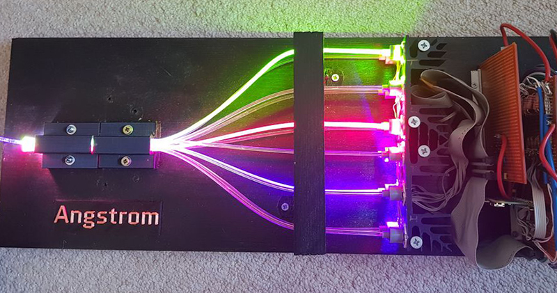
[ayjaym] over on Instructables realized anyone could buy a dozen frequencies of high-power LEDs, and the obvious application for this is to turn it into a tunable light source. The Angstrom is twelve LEDs, all different colors, and all controlled by PWM and piped down a single optical fiber. It’s an RRRRGGGGBBBB LED, ideal for microscopy, forensics, colorimetry, and seeing octoreen.
The heart of this device are twelve 3W star LEDs, with the following wavelengths: 390, 410, 440, 460, 500, 520, 560, 580, 590, 630, 660, and 780 nm. That’s deep red to almost ultra violet, and everything inbetween. These are powered by a 5 V, 60 W power supply, and controlled via a Raspberry Pi with 12 PWM channels in a circuit that’s basically just a bunch of MOSFETs. Proper heatsinking is required.
The impressive part of this build is the optics. A 3D printed mount holds and connects optical fibers and sends them into an optical combiner that is basically just a square acrylic rod. This is output to another optical fiber that will shine on just about anything. A webpage running on a Raspberry Pi sets the PWM channels of all the LEDs, and the resulting output shows up at the end of an optical fiber. It’s great if you want to look at something in a specific frequency of light. It also looks really cool, so that’s a bonus.


Don’t forget that colour is not a “specific frequency of light”, and the spectral emission of these LED’s is still pretty broad so for scientific purposes its not actually that useful. DMD tunable light sources are the winners so far if anyone is interested.
That said it does look very cool and I’m sure nearly everyone wants one to play with
Agreed. Adding different frequencies together may change what the color looks like to the human eye, but it doesn’t actually do anything to the base wavelengths… so likely helpful for some experiments, but not broadly useful.
s/octoreen/octarine/
https://discworld.fandom.com/wiki/Octarine
Some student chemical laboratories have LED based spectrometers, but the ones I’ve seen, don’t use this many different colors/wavelengths. Adding all of these should help with analysis I would think.
Colorimeters that use multiple LED light sources are not very accurate – especially for anything that fluoresces (like common paper).
Most spectrophotometers use a diode array or CCD array to detect light after it is dispersed by a diffraction grating, with the sample illuminated by continuous spectrum lighting (or a single wavelength at a time for a spectro-fluorometer).
“Most spectrophotometers use a diode array or CCD array to detect light after it is dispersed by a diffraction grating…”
The cheap and/or fast ones do, anyway, as do spectrometers, of course. But most decent spectrophotometers use a monochromator to select a single wavelength (rather, a narrow wavelength range) from a continuous spectrum source, and pass that narrowband beam through the sample, to be detected by a single detector (not an array). Generally, a tandem path with a blank sample is also used, to correct for incident intensity. A scan through a wavelength range can produce a spectrum, if desired.
Using narrowband incident illumination reduces scatter, improves dynamic range, and doesn’t confound things with sample fluorescence.
+1 for Discworld reference
Any estimates on how much power is lost in the optics?
The LEDs broadcast over about 4 steradians. Acceptance angle of the fiber is about 1 steradian. Without a coupling lens, there’s 75% lost right there. eff = 25%
Every optical surface interface loses 4%. There are 7 interfaces the light has to traverse: eff = 0.96^7 = 81%
The combiner reduces the area by a factor of 225/36. Because of conservation of etendue, and the limited acceptance angle of the exit fiber (assumed the same as the output from the source fibers), that’s 84% lost there: eff = 16%
The 6 mm square combiner output mates with a 6mm round output fiber, so 22% is lost at the corners: eff = 78%.
So even assuming zero loss in the fibers themselves, the net efficiency is around 0.25 * 0.81 * 0.16 * 0.78 = 2.5%
Lenses on the LEDs would help.
Optical coupling oil at the interfaces would help.
A lower reduction ratio in the combiner would help, and combining with dichroics will assist.
A larger output fiber to match a larger combiner output will help.
Or can run (say) 6 fibers to each led, covering nearly a half-sphere around each, capturing half or more of the light, and bunch them into a randomized 72-fiber bundle output (25 mm diameter). You get better capture of the LED light, few interface losses, and no combiner loss, at the cost of a somewhat harder-to-handle output fiber. Ten or twenty times the light output though.
I wonder what the spectre looks like…
Is that the plural of spectrum? Latin is soooo confusing.
Don’t forget that a prism will take them apart at the other end…
Realy octoreen. This is why people look at articles like this and think FAKE. Can’t mix in fake with the real that’s why people are divided.
Gargle returned octarine when I searched for octoreen…
I think people are divided because they’re a bunch of yutzes who can’t, or forgot how to, separate the fake from the reality.
“It’s in print so it must be true!”
“OMG Becky, they made a joke so how can I take them seriously now??”
They all look white to me in the picture. Once again over-exposure ruins the color. To take a picture of light sources one needs to stop down several stops. In the digital realm there is HDR which will take in the colors and the darker background. One average weighted picture can’t do it.
I built electronics for one of these in 2002 at $company. We used an integrating sphere, but the same approach to driving. Lots of fun! Also lets you see the difference between radiance and luminance in a very clear way – hold optical power constant while ramping wavelength past the end of the visible range.
Pics or it didn’t happen! Oh wait.
I’d love to see that in person. The closest I’ve come is some laser shows where they blend 5+ colors instead of the usual RGB.
:) The great thing about an integrating sphere is that they are very boring to look at ;) . Assembled, it was a case about a foot on a side with a circular opening on the front. But any color you liked would come out of that circle!
“You can search LEDs by frequency,”
Actually, Mouser & Digikey allow parametric searching by wavelength, not frequency.
There are two unchanging constants in the universe. The speed of light, and the pedantry of Internet commenters.
Hackaday needs a +1 button for comments like this.
“The speed of light in vacuum” FTFY
Actually, the speed of any massless particle…
I see what you did there.
Here’s another good one: when anyone says patronizing, you say with with disappointment in your voice “that’s actually pronounced pah-tronizing” or “pay-tronizing” depending on the situation. Cracks me up every time.
Wouldn’t that then be something along the lines of UVVVBCGGYYORIR?
lol
And a wickedly high CRI.
Or is that your new password?
Well played with the light combiner! Really clever solution. One purpose for this device (if the light intensity is high enough) could be as an excitation light source for fluorescence microscopy.
Although using PWM might be an issue for short exposure times (unless the PWM frequency is in the 100KHz – MHz? range). As far as I know, that’s why current control is normally preferred.
Also the LED emission profiles are quite broad, so band pass filters are (usually) used right in front of each LEDs… and the light is bounced off of another set of dichroic filters all the way to the fiber port. Have a flash animation (ha!) to see what I mean: http://zeiss-campus.magnet.fsu.edu/tutorials/colibri/indexflash.html
All these add to the bulk and cost of the unit, and you rarely find more than 6-8 bands in a commercial offering. They might cost between 6 and 12K depending on the number / power / wavelengths of LEDs. Still a lot less than the cost of a whole microscope…
It’s a shame the light coupling efficiency from LEDs to output is so hideously poor. The OP is obviously aware of the problem, and uses the right term etendue describing it, but apparently didn’t need high efficiency badly enough to put the engineering effort in.
Larger fibers would help a lot, as would dichroic combiners mentioned above, but the optics start to get large and expensive. The 3-LCD color image combiners from large video projectors work nicely for this, and are available surplus, but you need a fairly narrow beam launched into them (like f/4), but that’s not far off the maximum a fiber will accept anyway, so they might be a good match.
As the OP I was interested to read the comments. It’s a project with tradeoffs; precision optics cost large amounts of money unfortunately. I don’t think the fibre coupling losses are as great as stated though. The LEDs radiate over a broad angle but most of the output is actually within the capture area of the fibre. If you place your hand over the 12 fibre outputs there’s sufficient optical energy that you can feel it (i.e by the heat generated), which as a rough ballpark I would think is several hundred milliwatts of radiant energy. I think we’re losing maybe 50% but I don’t think 80%.
It’s possible that collimating lenses on the LEDs might help; this does push the cost up though. Getting the fibre closer to the LED chip would also be desirable but would require some careful filing down of the encapsulation and some of the LEDs have soft polymer domes which deform easily, snapping the bonding wires. Also possibly collimating at the coupler end for each fibre to reduce the approx 45 degree exit angle might help. If someone is able to figure out a way of improving efficiency cheaply I’d certainly be interested to check it out though. On the PWM side, I’ve just published a sister project (Dupin) that uses a true constant current source (non PWM) to power a set of clip on LED heads, so only one wavelength at a time but you could probably hook up much more efficient fibre coupling to those if desired and the current source is also able to be modulated up to around 1MHz for pulsed applications as well.