One of the vast untapped potentials of medicine is the access to imaging equipment. A billion people have difficulty getting access to an x-ray, and that says nothing about access to MRIs or CAT scans. Over the past few years, [Jean Rintoul] has been working on a low-cost way to image the inside of a human body using nothing more than a few electrodes. It can be done cheaply and easily, and it’s one of the most innovative ways of bringing medical imaging to the masses. Now, this is a crowdfunding project, aiming to provide safe, accessible medical imaging to everyone.
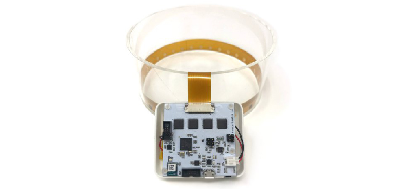
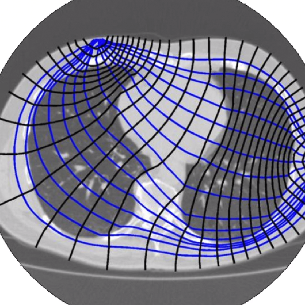 It’s called Spectra, and uses electrical impedance tomography to image the inside of a chest cavity, the dielectric spectrum of a bone, or the interior of a strawberry. Spectra does this by wrapping an electrode around a part of the body and sending out small AC currents. These small currents are reconstructed using tomographic techniques, imaging a cross-section of a body.
[Jean] gave a talk about Spectra at last year’s Hackaday Superconference, and if you want to look at the forefront of affordable medical technology, you needn’t look any further. Simply by sending an AC wave of around 10kHz through a body, software can reconstruct the internals. Everything from lung volume to muscle and fat mass to cancers can be detected with this equipment. You still need a tech or MD to interpret the data, but this is a great way to bring medical imaging technology to the people who need it.
Right now, the Spectra is up on Crowd Supply, with a board that can be configured to use 32 electrodes. Measurements are taken at 160,000 samples/sec, and these samples have 16-bit resolution. This is just the acquisition hardware, though, but the software to do tomographic reconstruction is open source and also readily available.
In terms of bringing medical imaging to the masses, this is a very impressive piece of work, and is probably the project from last year’s Hackaday Prize that has the best chance of changing the world.


The images are not so pretty. they need finer resolution. Think of what your computer monitor would look like if it had 32 columns on the screen. Just sayin’, I don’t have a solution.
Shouldn’t be that difficult to increase the resolution – just a matter of adding more multiplexers.
Do half-stepping? send 50% of the signal from a point and the other 50% from the next point, then 25% / 75%, etc.
2**n -1 combinations. Its tomography. That’s 4,294,967,295 from 32 electrodes.
Uh, no. The number of pairs is quadratic in the number of electrodes, not exponential. Specifically for n electrodes there are n*(n-1)/2 pairs, i.e 496 in the case of 32 electrodes.
this n*(n-1)/2 is right, though there is the addition of there being 4 electrodes to do each measurement to include common mode rejection. There will be an article on exactly this coming on monday through crowdsupply mailing list: https://www.crowdsupply.com/mindseye-biomedical/spectra
You can get more resolution than that though – between each pair of electrodes you can measure more than just the DC resistance – you can measure AC impedance at an infinite number of frequencies. The math of exactly how you put that data back into an image might be computationally infeasible though…
Yep, and over a frequency sweep you get dielectric spectrums. I don’t think they’ve figured out how to use that information as you say so you get lots of useful information about what materials are present, but it’s hard to integrate into a simple image.
Spectra is using a single AC frequency to do an image reconstruction, though it can separately also do frequency sweeps between 100Hz through to 80Khz.
If you look at early images of MRI’s or CATscans they will look similar.
Here is an image of lungs from the earliest MRI scan: https://two-views.com/images/MRI-ics-48.jpg
Also an interesting article on how MRI was developed: https://two-views.com/mri-imaging/history.html
It has certainly come a long way!
I will be writing an article on the history of medical imaging improvements and how they made it into the mainstream on the crowdsupply mailing list in the not too distant future.
Also, using a one-dimensional linear array to attempt to solve an intrinsically three-dimensional problem is certain to involve assumptions and approximations.
A full 2-D array of electrodes is necessary, unless you make the assumption your scanned subject is constructed solely of infinitely-long cylinders.
What I have to wonder is, how quickly, easily, and accurately the electrode can be wrapped and unwrapped. That’s a tricky part for the fancy radiation-based imaging too, how to get many slices quickly with minimal anatomical change/distortion.
Just lay the patient in a bed-of-nails fixture. :-)
The good thing is, the nails don’t have to be sharp. Metal patches would be better.
Such a revelation, I thought all this skin was just a waste, but now I realise I’m really covered in test points.
I agree – putting electrodes on is annoying. Another idea is just to submerse the person in a conductive bath…. the conductive bath has electrodes around the sides with known geometric positions, to make solving for what’s inside with accuracy a bit easier.
Sounds like the field of wearable electronics and cheap medical could get together.
Yeah, I did this Spectra project, and my background is actually biosensor wearable products. I got a bit bored of just the basics of heart rate and accelerometry and think this is the next area.
Any health hazards like the CT scan ir XRay?
No, it uses very low power, low frequency electricity. Too low to feel. Like an ohmmeter.
Hmmm. Interesting but doubtful on first blush. Image reconstruction from projections has a sound physical and mathematical basis. Primary is that there is a straight line from the source to the detector. I just can’t picture it using conductive paths through organs. I suspect such paths vary in non-linear ways.
I would very much like to see the analysis they used to develop their equivalent of deconvolution (which is linear).
It’s true current is not flowing in straight lines, but you can apply filtered back-projection which does assume linearity and get a picture(same algorithm used in CATSCANs). If you wish to model the current flow more accurately you can use a finite element model and a Gauss-Newton iterative solution. Spectra has 3 algorithms that run in real-time that come with it. 1. Filtered Back Projection 2. Gauss-Newton 3. Graz Consensus(a slight update on Gauss-Newton)
Forgot to mention – non of these algorithms are perfect at all and all make varying levels of assumptions, but each is better than the last.
Do you have a reason that it should work? Some idea you are attacking from?
it already does work – you are welcome to look at the reconstructed images on the project entry https://hackaday.io/project/159737-spectra-open-biomedical-imaging. The resolution isn’t as high as a CATSCAN with 32 electrodes(a CATSCAN has 256 and also rotates those to make more effective electrodes). This technique is in it’s infancy though, so perhaps making an open source project out of it will inspire others to improve on where it’s currently at also.
I saw the project page. Here is my difficulty: If you put an opaque cylinder in a sample in tomography, projection and back-projection will show the shadow of the cylinder because the signal path is blocked. If you put an empty or non-conductive cylinder in your system, the current still flows. It is not blocked and just takes a path around. I don’t see how tomography can be applied.
Honestly, I am suspicious you are getting an artifact of radial symmetry. I hope it is working, but need some geometry and math to back it up. How about punching a hole in a fruit with a plastic pipe? Or some membrane tube in water with a different salinity or pH? If round hole looks OK, do triangle (prism) or square and see if the rubber meets the road.
I played with Jean’s prototype at a recent meetup. The demo involved locating a shot glass being moved around in a dish of saline. Remember that in a conductive medium, a “hole” still results in a change of current path and therefore a change in complex impedance. Jean’s hardware does not simply measure conductive/nonconductive, it measures varying degrees of conductivity and also runs frequency sweeps to measure reactance.
If you look at those string-art portraits that are based on a simple ring of nails and thousands of carefully-chosen thread positions, that would be a simplification of the back-projection algorithm.
The fun thing is how much of an enabler the (cheap) GPU has been towards all this. Thank you gamers!
If you had a rock with a fossil inside, would this device show that?
If the rock conducts, maybe
Or if the rock was porous enough (but the fossil does not need to be) to absorb salt water, then maybe.
EIT of the lungs is already in clinical use: search for Dräger Pulmovista.
The Resolution seems to be higher.
Interesting that they don’t have that many electrodes, looks like about 18.
I did the same thing, but for DC measurements – the target use there is measuring lots of resistive sensors using a minimal amount of cabling (the total amount of sensors usable with N wires is N*(N-1)/2 ). See: https://www.daqq.eu/?p=1333
Super interesting. Yeah this is very similar to electrical impedance tomography. One of the testing mechanisms they have is a resistor phantom where they basically do this but on a larger network scale.
X-ray computed tomography imaging went from a napkin sketch to clinical application in four years, despite concerns over radiation dose and the very serious handicap of sufficient computing power in the early 1970s. Since 2005 or so, cheap computing power and the new algorithms it affords have enormously improved image quality, speed, and even dose.
Electrical impedance tomography has been seriously attempted since the before the early 1980s — I attended a talk on it in 1982, when it already was being trialed in several locations. Despite the glut of computing power, relative ease of implementation, and zero radiation dose concerns, it has yet to gain significant traction.
One might infer there is a fundamental reason for this difference. (hint: it’s not concerns over imaging manufacturers’ profits)
Yeah, maybe Jean should build yet another CT scanner right? that would really be something….
There are new algorithms coming out in EIT and a recent one is the D-Bar algorithm which is more robust to contact impedance issues – https://arxiv.org/abs/1404.5978. Another recent paper showed even better results combining D-Bar with a neural network. There were people who were dubious that the neural network was trained properly, though it would make sense that Maxwell’s equations could possibly be modelled this way with enough data.
One other way to get around the contact impedance issue is to use a tank with water, where the contact surface area of the electrode with the conductive medium can be accurately known. The tank makes a good test set up to make better algorithms to solve the generalized problem. I also agree that multiple frequencies should be used to obtain dielectric spectrums at every voxel, but haven’t seen a good algorithm that recombines this data into a unified image as yet, as it gives too many dimensions to use classical solvers.
I would guess it has to do with a lack of unique solutions or “close enough” solutions. Either unsolvable, or not enough information to solve no matter how dense the sensor array. Some things lend themselves to deconvolution and some don’t. X-ray tomography had a considerable workable theory and those rotating photographic plate things (axial transverse tomography) that some people had learned to read. [Image Reconstruction from Projections by Herman was written in 1980 and is pretty exhaustive mathematically, even though new and improved algorithms continue to be developed.]
“by sending an AC wave of around 10kHz through a body, ”
Using just a single frequency is missing some of the richest data of EIT: there are three distinct plateaus in the EIT spectrum, each probing different environments in the body: Near-DC frequencies (<>1000). Higher frequencies more easily see capacitive effects, such as fat layers and cell membranes, but are largely excluded from cell interiors because the cell membranes act as capacitors that still block relatively low (<> 1 MHz) “see” through the capacitive cell membranes, and thus can measure the resistivity (rather, the complex impedance) inside cells. These higher frequencies see the “true” permittivity of body water, around 70. This permittivity is roughly constant until the big water absorption peak around 15 GHz, though penetration depths start to drop off markedly after 200 MHz, so these higher frequencies are not useful.
I would think that in an ionic fluid, the AC up to several MHz will generate Maxwell induction currents, a physical shaking back and forth of molecules (as opposed to rotating molecules in microwave), which in turn will have localized effects due to these currents. Sounds like a mess. If there is a theory, I would like to see it.
Not induction currents (i.e., due to alternating magnetic field): conductivity is way too low and skin depth is many, many meters. You may be thinking of Maxwell’s notional “displacement current”, manifesting as alternating currents of ions under the influence of the electric field, which IS a dominant loss mechanism in the mid-frequency range (~1 MHz). The dielectric loss tangent of water dominates at higher frequencies (though ions also play a large role even well into the GHz).
The bioimpedance analysis literature has been pounding at this for well over a century. One starting point: https://www.ncbi.nlm.nih.gov/pmc/articles/PMC4118362/
If you’re interested in the dielectric properties of tissues at various frequencies, the Gabriels pretty thoroughly covered it. One entry point to the rabbit hole is here: http://niremf.ifac.cnr.it/tissprop/
You are right, I was thinking the displacement current. My first job out of school was to analyze what was really happening in big 100kW RF glueing machines (Mann-Russell) in continuous laminated beam presses. They ran at 1MHz and they had called them microwaves fro want of any other explanation. Mann was a high school shop teacher when he invented the process and it was a matter of experimentation and iteration. And no science to speak of. (George Russell was the brother of Frank Russell Co.)
Checked the description. If you have a completely unknown object you want to image its inners and you cant predict the path of your currents (because of its unkown heterogenous nature), what can be the result? Even if you throw more sensors of the same type at it? There is a serious uncertainty of information in the input data which can’t be balanced with filtering algorithms and leads to wrong deductions about the structure of the object . Sorry you cant defeat the laws of nature. I seriously doubt the this technology can get anywere near CATSCAN/MRT. All I see is a sophisticated object detection that produces funny moving pictures. Thats enough for collecting money. Sorry.
The thing of it is, it runs at low enough data rates that you can use cell phone like processors, and it doesn’t need a huge amount of expensive machinery, high strength magnets cooled by liquid helium, or x-rays. The part about being low-resolution, well, they gotta work on that.
I did GPR for some years and once we hired a guy to use a similar technique to figure out what was underground. Of course he had only the surface to work with. He pounded in a bunch of electrodes and measured the resistance (at low frequency AC, don’t remember exactly the f) and fed them into his laptop. He figured there were 4 distinct layers of soil and rock down to about 100 feet. Wet topsoil, sand, glacial rubble, bedrock, something like that. It’s all in the spacing.
I am not going to claim to know much about all this, but it seems like a great idea. About the resolution bit, maybe something like a cylinder pillow-like material could be used between the body and the electrodes, allowing the electrodes to rotate around the body while still maintaining contact? I have no idea what could be used, but i’m sure there are materials allowing for such a thing. Basically something that can transform the geometrically difficult human body into a cylinder that “test pins” can rotate on. I am sure some initial calibration should be able to compensate for this additional layer of material.
Yes – a CATSCAN does exactly this by rotating around your body. I didn’t do that as that’d be more infrastructure to try but it’s a good idea. I wrote a post about other ways to get to better spatial resolution here too(using mathematical modelling approaches): https://www.crowdsupply.com/mindseye-biomedical/spectra/updates/safety-and-the-path-towards-better-spatial-resolution