A favorite project of ours is the humble breadboard power supply. Yes, you can still prototype on breadboards, no, you don’t need an entire bench power supply to prototype on one, and every breadboard made in the last forty years has had the same pattern of holes. There’s plenty of opportunity to improve the breadboard power supply.
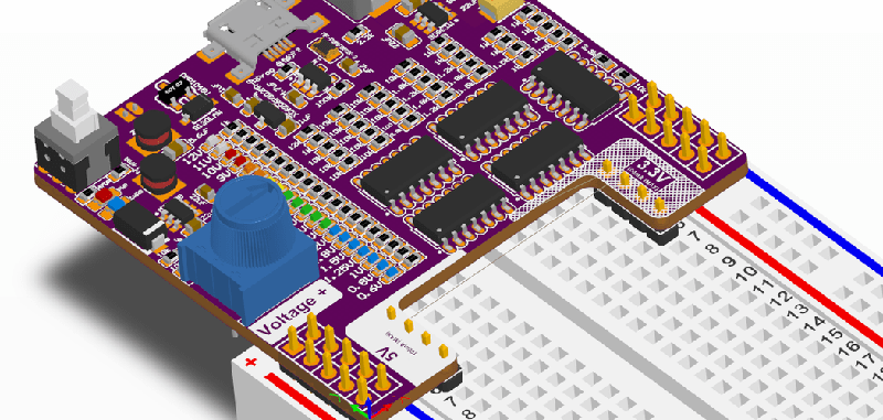
One of the best ones we’ve seen yet comes from [John Loeffler]. It’s a simple, constant voltage power supply that’s variable from 0.6 V all the way up to 12 V. It’s powered through a micro USB port, and you get 3.3 V and 5 V rails automagically. There’s even voltage indication.
The mechanical design of this power supply is simple enough, with pins that plug into the detachable power rails on either side of the breadboard. Where it gets interesting is the voltage indication. There’s a resistor ladder and a series of LEDs to indicate the voltage on the variable side of this power supply. Add in some modern switched mode power supply based on the MIC5225 series of chips (a popular regulator that’s very nice for the price) and you have a completely functional power supply hanging off a breadboard.
While it’s not a really nice rack mounted bench power supply that weighs a lot, or even one of the cheapo bench supplies, this does fulfill a need. Sometimes you just need a simple power supply for a breadboard, and this is one of the best ones we’ve seen yet.


“…constant voltage power supply that’s variable…” :-D
yup. As opposed to a constant current supply. Set the voltage and it is maintained as current (load) varies.
Yes I know what it meant, the words just amused me.
I added a Constant current Potentiometer to this But the components are a little more dense and will have to go down to 0402
Constant Power (CP) can be even more interesting and especially so with motor testing eg ramping and to a lessrl degree though still fascinating in electrochemistry :-)
english is such a wonderful language!
Add on an ftdi chip and you’ve got a great unicersal development board.
In my 3rd version I use the SAMD21 which has a usb uart built in. Also has a full color current and power display.
https://hackaday.io/project/164700-open-power-prototype-3
The voltage indicator part is quite component-intense. You could simply buy a cheap meter module from China, but well, if you like individual LED…
What is really missing is a adjustable overcurrent-protection. You need this to not fry your parts if something goes horribly wrong.
I am currently routing a version that has Constant current on the Right Side. Ill upload that in the next week
You have to be careful with the type of LED voltmeter modules that you are buying. Some of the earlier more expensive ones uses a STM8 which has a 10-bit A/D (0-2047) and should have quite decent resolution. The really cheap ones seems to be using a micro with only 8-bit (i.e. 0-255). I have used one on my homemade linear supply and the voltage values skips as they scale the 8-bit value to fill the 3 digits. It wasn’t too accurate either.
You also have to mod to use a separate supply rather than than powering from the input as it won’t get you the lower voltages at all or accurately until the linear regulator can generate a regulated voltage (say higher than 7V for the old 7805 types).
I don’t like this at all. Sorry to be a misery, but it is all bling at the cost of function. A volt meter with some other stuff tacked on. Save all the board space with the paraphernalia and just provide a simple rotary switch with the common voltages. It doesn’t even state what current rating is available, what use is that? I looked up the MIC5225 and it says 150mA, well that is wholly inadequare – our friends the Espressif chips need 3 times that much.
Mike, Thanks for the feedback, I will look into a better ldo with a higher current rating. I am currently working on a Constant current Limit and will have that designed by the end of the week.
well, it turns out that not al breadboards are created equal. I have two where there is more space between the prototyping area and the power bars. I found that out after ordering a power supply pcb from ali that didn’t fit. after tweaking on of the two pin headers that problem was solved, but i’m limited to one power supply voltage.
Actually I always use a contra for the barrel jack with four pins soldered on, directly sticking into the power bars. I use a benchtop lab power supply to set the voltage.
That’s exactly what I came here to say! All breadboards are identical except apparently for mine… :P And yours!
Why not used a pair of LM3914s instead of 20 opamps with a resistor divider?
The simple answer is cost LM339 are less than $0.05 each
The divider values are different, i.e non-linear scale.
Not a good design for manufacturing (if intended as a product). More components costs more (low volume places charges by number of pads/solder joints). and lots of different values need to stock multiple reels.
Brian Thank you for the review,
I am working on 3 Prototypes simultaneously and i have a version with +- adjustable rails that has current limiting for both and a TFT Color Display.
https://hackaday.io/project/164700-open-power-prototype-3
This version currently does not have constant current but i added that functionality in the latest revision.
The reasons for the component density is cost. Right now 5 lm339s and a couple of leds cost less than an mcu (not including an oled). I wanted a version that did not need to be programmed.
On other thing is that all my verions have a lipo backup and the usb can be disconnected and it will still be powered.
> every breadboard made in the last forty years has had the same pattern of holes
[citation needed]
My father gave me some breadboards that he bought in the early 1970s, and other than the discoloration of the plastic from age they were identical to the ones I purchased 2 years ago.
I know that’s not really a cited source, but anecdotal evidence should be better than none in this case, IMHO.
More anecdotal evidence: I got my first breadboards in the mid ’70s. Virtually identical to the ones I’ve bought in the last few years.The older ones seemed to be more robust though
I have a few that only have a single power rail on each side. From the 80’s as I recall
Good idea, but……
Embedded systems development is found at the intersection of code madness and circuit delirium. You do not need another uncontrolled variable during project development. The bench power source must be robust, reliable, and safe. Test and debug your project, not your power source.
While I have built a full-featured bench-top power source, it was done for where commercial units could not provide the very high isolation and very low leakage of a specific project; and the design was based on some HP power source circuits. Ultimately I prefer to buy used HP units for my bench.
> Embedded systems development is found at the intersection of code madness and circuit delirium.
I am totally stealing this quote. I feel at home here.
He forgot to add ‘client delusion’. I suspect traumatic amnesia. :grin:
I don’t think this would ever replace a bench-top power source. Benchtops are clean and reliable bit in no way are they portable or cheap.
This is usb/ Lipo powered with load sharing so it can be disconnected while using it.
For portable mobile projects or for demo-ing something on a breadboard. I wound not recomend bringing your benchtop with you.
I do get the concern of reliability and safety and intend to improve on that in the coming weeks.
The faux outrage is strong here. Who cares, honestly?
You’ll never know the voltage setting before you turn on the power. I would prefer to use a fixed voltage regulator.
If I had to use a trim pot, I would use one without a knob( i.e. use a screw drive) and not having to worry if accidentally turn it higher voltage while working near the knob.
I would rather have jumper selectable voltages via fixed resistors than a low resolution bargraph. LED could have been more far useful to show logic levels (via some buffering).
That is a good point maybe i could place tick marks on the knob. I prefer the knob because i don’t need a screwdriver on hand to change the voltage. As for bumping into the potentiometer. These knob ones have a pretty high resistance to turn compared to standard potentiomerters with the added benefit of being compact.
So what are the part numbers of U3, U4, and U5? What is the part number of the undesignated chip used for the separate 3.3V schematic? Sorry to post the questions here, but I don’t like being forced to manage yet another account just to post a comment on hackaday.io.
So what are the part numbers of U3, U4, and U5? What is the part number of the undesignated chip used for the separate 3.3V schematic? Sorry to post the questions here, but I don’t want to have to manage an account just to post on hackaday.io. [This may be a duplicate post, the comment system is NOT working well for me these days here on HaD, way too much scripting bloat, yuck.]
Can probably figure out from the layout: https://cdn.hackaday.io/images/2596791555427706296.PNG
– U3, U4 have the same symbol and based on functionality are the MT3608 (1.2MHz bost converter)
– U5 looks like a LDO, so MIC5225-5.0 by eliminating the two others that are labelled.
@tekkieneet, Yeah thanks. I just came back here to post the same thing. After going back and forth between the schematic, the first project log post, and the board drawings, I came to the same conclusion. I just wish the Author had annotated the drawings properly to begin with.
Or uploaded the design files. Another content light had.io post. Yay!
I will within the week
I apologize i will make the corrections to the schematic
The real interesting thing for here for me is the work done by someone else in hacking the normal topology of the ubiquitous Chinese MT3608 boost converter. The O.P. references this work in the first project log entry on the hackaday.io post. I’ll reiterate the link here to save you time:
https://mysku.ru/blog/aliexpress/36199.html
The page link above seems to be in Russian. Google translate does a credible job with it.
You can try this Google Translate link – but no guarantees. If the link doesn’t work for you just start a new translation. Remember to back-off your script blocking browser add-in at bit [e.g., uMatrix or Noscript] or you won’t get the final result:
https://translate.googleusercontent.com/translate_c?depth=1&rurl=translate.google.com&sl=auto&sp=nmt4&tl=en&u=https://mysku.ru/blog/aliexpress/36199.html&xid=17259,1500010,15700002,15700021,15700186,15700190,15700253,15700256,15700259&usg=ALkJrhhCan8fgNvXyt4Tp3R9JNaVYjNFeA
Thanks for pointing this out. In fact this source is what both MT3608 are based off of because both use either 3.7v or 5.5V so a sepic converter was required to get a regulated 5v. I got pretty good loaded performance of less than 30mV ripple.
(2**8)-1 = 255
(2**10)-1 = 1024
(2**11)-1 = 2047
https://xkcd.com/386/
Someone has to say it. 1023.
;-)
> Add in some modern switched mode power supply based on the MIC5225 series of chips
Brian, the MIC5225 is not a switching regulator, but rather a classic LDO. These get confused sometimes but they are quite different in terms of cost, complexity and features. See https://www.rohm.com/electronics-basics/dc-dc-converters/linear-vs-switching-regulators for a quick comparison.
Also a quick glance at the project page seems to suggest that it uses an MT3608 which is indeed a switching regulator. The LDO only seems to be used to derive 3.3V from the 5V rail (I think).
(2**10)-1 = 1023
This is a reply to Duty Calls. If this reply does not go as a reply to Duty Calls message, then WTF? It’s happened to me twice already, that the replies are not actually set as replies, but as new messages. This really sucks. It even says “Leave a Reply to Duty Calls”
I would prefer something like a resettable fuse that trips when the current is over some (configurable) threshold. Constant current is good for battery charging, for saving expensive (or not) components something like a fuse is better imho. I’m still thinking about modding my PSU for this.
A resistible fuse is integrated. I was looking into using a small relay that will trip when more than 500mA is used by usb with a pushbutton to reset it. It will switche to the battery which can output significantly more current.
I would prefer something like a resettable fuse that trips when the current is over some (configurable) threshold. Constant current is good for battery charging, for saving expensive (or not) components something like a fuse is better imho. I’m still thinking about modding my PSU for this.
I have designed a power system with a hiccup (cutoff with auto recovery) scheme but a small amount of retries before it shuts down. It reduces nuisance trips into large bulk capacitors, but limits the amount of damages.
There are also foldback (thermal protection for some linear regulators), constant current, hiccup (thermal protection for some switch mode supplies) and one time fuse.
Why is this going here?? It’s an answer to John Loeffler April 20, 2019 at 12:25 pm. Stupid comment system.