Potentiometers, or variable resistors, are a standard component that we take for granted. If it says “10k log” on a volume pot, than we fit and forget. But if like [Ben Holmes] you are modelling electronic music circuitry, some greater knowledge is required. To that end he’s created a rig for characterising a potentiometer to produce a look-up table of its values.
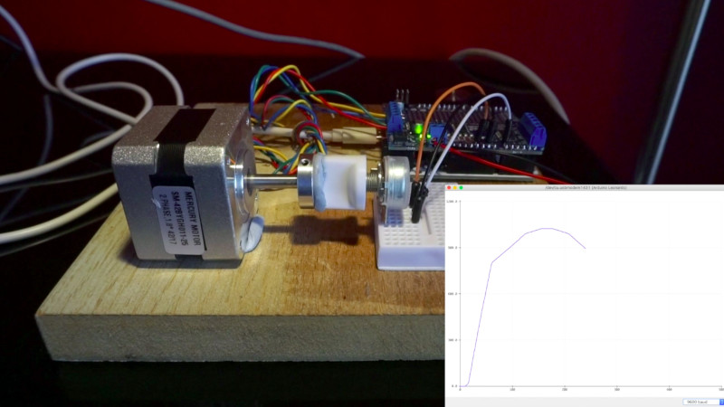
It’s a simple enough set-up in which a voltage controlled current source feeds the pot while an Arduino with a motor controller turns it through a stepper motor, and takes a voltage reading from its wiper via an analogue pin. Probably most readers could assemble it in a fairly short time. Where it becomes interesting though is in what it reveals about potentiometer construction.
Audio potentiometers are usually logarithmic. Which is to say that the rate of change of resistance is logarithmic over the length of the track, in an effort to mimic the logarithmic volume response of the human ear in for example a volume control. If you are taught about logarithmic pots the chances are you’re shown a nice smooth logarithmic curve, but as he finds out in the video below that isn’t the case. Instead they appear as a set of linear sections that approximate to a logarithmic curve, something that is probably easier to manufacture. It’s certainly useful to know that for [Ben]’s simulation work, but for the rest of us it’s a fascinating insight into potentiometer manufacture, and shows that we should never quite take everything for granted.


Very interesting. I didn’t know they were still made this way, since most current manufacture methods should allow for a smooth curve. I remember (and still have a few around, for that matter) the old wirewound audio taper pots with several wire sizes and variable spacing on the turns to approximate the taper.
The reason is that that while you can make an “ideal” taper to the track, variances through tolerances put it out of whack very quickly.
The potentiometer’s wiper is a point contact – not ideal. The wiper goes around in a circle, so you’d have to match the taper exactly to that so the wiper moves along the track in a symmetric fashion to avoid errors due to the fact that the resistance to the wiper depends on where exactly you press it – if it’s closer to the edge, current is pinched off from that side and the contact resistance is higher. Further problems come from the fact that you can have more than one wiper to the track, so when one bounces the other is still in contact. If the track tapers narrower, the sidemost wipers will fall off of the track.
So, another option is to make the track slope instead of taper, but that’s very difficult because a logarithmic pot needs to grow in thickness… logarithmically. Suppose you’re trying to do 2^n and at first the track is .1 mm thick. Five octaves higher it’s 3.2 mm thick and the wiper can’t follow such a slope, except on the flat backside. This is actually a problem for the tapering width track as well – the track quickly grows out of bounds or becomes too narrow and frail for the wiper.
But then how are you going to mount the track onto a substrate when it’s so much thinner at one end? It gets fiddly and expensive to manufacture really quickly, and when it wears out through use the track is going to get thinner at one end proportionally faster than at the other – so the logarithmic curve will go out of calibration very quickly.
All that is avoided if you make the track circular and even in thickness and width – less mounting and centering issues, wears more evenly – and then simply vary the resistivity of the material as you go around. That way the track can be made with traditional photolitography methods onto a piece of flat resin and no machining is required.
I’m not picturing your widths and depths very well. There were wire wound log pots with the mandrel circumference changing as the log so that the amount of wire per winding increased correctly. Maybe that is what you are saying.
Wire wound pots still exist, but most pots are made from conductive resins, polymers with carbon or metal particles mixed in. These resins are printed onto flat pieces of PCB or other carrier boards.
You could stamp a plastic carrier with a void in the shape of a logarithmic ramp and then cast it full of the resin, but it would still be unwieldy to make and prone to a host of problems.
I have previously had the joy of cleaning the faders on an MBI series 12 desk (https://www.allen-heath.com/media/IDR_16_32_48_64-MBI-SERIES-12-MANUAL-AND-SCHEMATICS-PART-1.pdf – warning 7.5MB PDF!), which use an interesting log approximation design, with a linear high resistance track, tapped off at regular intervals into a chain of lower valued resistors, which set the ‘taper’ curve. This permits a good quality multi-finger wiper, on a wide track, while retaining the pseudo-logarithmic fader curve.
I can’t see a single schematic there.
funily enough t=just today I was trying use an audio pot for something that realy needed a linear pot. It works but the scale isnt the nicest…
About a year ago I paid about EUR 20 for a WDD35 potentiometer with a linearity of 0.5%.
It looks quite beautiful on the inside, with ball bearings and conductive plastic track which is milled to width for calibrating linearity. Quality costs money and you get what you pay for.
For this sort of potentiometer it’s quite cheap. comparable potentiometer can cost EUR 200 or more.
These potentiometers are not meant to be fiddled by human hands, but are meant to be mounted on motor shafts or other machines, can rotate continuously and are rated for tens of millions of revolutions.
There’s a way to combine a linear potentiometer with a resistor to make something that’s more “log” than what commonly are sold as log potentiometers.
http://sound.whsites.net/project01.htm
You beat me to it. Tons of great projects and into on that site.
Thank you for making this, and for posting it! I’ve had a very similar idea kicking around on the back burner for eons, and never got around to it because I didn’t have a good way to plot the results. Of course now that I think about it, I’ve learned a bit since then and I think I might have to give this a go!
Good info and system to consider. Kind of like agriculture, food and drugs (we hope as medicine of course… amazing how has to be clarified to the recovering or do gooders)… when I got started in the study and industry I was amazed at the range of variation in quality and I think even more-so with electronic components how really there is the need to test each component before soldering since the variation is so great. Especially smart to consider with higher accuracy systems and/or higher frequency systems too.
“Which is to say that the rate of change of resistance is logarithmic over the length of the track”. The pot should have distance proportional to logVin. A rate of change proportion to distance for a log pot will have output proportional to 1/V
A curious coincidence. Not only could I set up a system like this, but I have. I am characterizing the potentiometers in an old Faro arm.
My setup is a bit crazy, I happened to have a huge NSK Megatorque servo with a super high resolution encoder, so I am using that. It makes 147Nm of torque, though so I am using deliberately weak 3D printed fittings.
Voltage is measured by a 32 bit SPI ADC and then an Adaffuit ItsyBitsyM4.
These pots are astonishingly linear. Excel reckons the R^2 is 0.999995
I seem to recall there were linear, log, and semilog pots. But since everything’s digital now, why bother with pots? Use a quadrature encoder and do whatever “taper” you need digitally, right? I’m a retired EE whose worked on this stuff since the early 70’s, and I don’t miss those over-priced, clumsy, noisy, and unreliable pots one bit!
Because then you need an arduino to make a 555 bugle that scales linearly in tone.