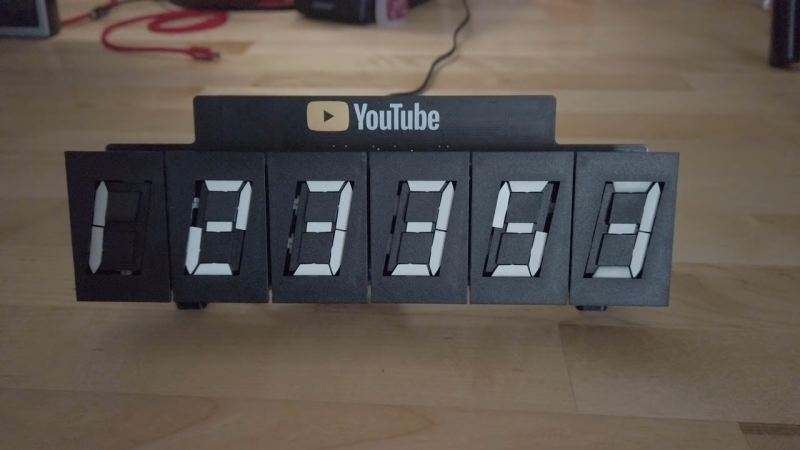
Acquiring a new YouTube subscriber is a blessed event that deserves far more fanfare than a phone notification. But maybe blinkenlights don’t really do it for you anymore, or you simply prefer to be soothed sonically rather than visually. Well, what could be more satisfying than the crisp clack of an electromechanical 7-segment display? Six of them, of course. These things look great, they sound great, and once they’re set, they don’t need power to stay that way.
These displays switch between black and white by reversing current flow through their electromagnets, so [Zack] turned to the H-bridge in order to use them with DC. One H-bridge for each segment of six displays adds up fast, though. To get around this, [Zack] tied one pole of each electromagnet together for a common signal input, and used the other pole to control each segment individually. Then, he was able to tie all the A segments together, all the B segments, and so on, and only needs 13 H-bridges to do it all.
There was just one thing [Zack] didn’t count on. Once he got the board soldered up and running, the displays started acting funny. The low impedance of the coils was causing them to influence each other over the common path, so he added diode arrays to keep them in line.
[Zack]’s using an ESP32 to get the 411 through the Google API, and four octal serial switches to drive the displays. Even more satisfying than all those clacks is the displays’ operational economy baked into [Zack]’s code—as they count up, any segments common to the first digit and the next digit remain on. Increment your way past the break to check out the build video.
Not focused on numbers, but still want to celebrate each new sub? Try a dancing robot or a Tetris twist.


That title tho 👌🏽
Nice project!
Your lab setup is awesome as well…
I didn’t realize the modules were so small, I’d love to see him make a calculator with these displays.
The low impedance of the coils was causing them to influence each other over the common path, so he added diode arrays to keep them in line.
Hunh? I had to watch the video to hear what Zack really said but, yup, he said the same thing. Didn’t make any more sense to me when he said it either.
He doesn’t say where he’s sprinkling his magic fixit diodes, so it’s hard to understand what the original problem was and how they fixed it.
I’m guessing the real issue is the inductive spike from turning off a coil is propagating back through the MOSFET body diodes.
Since the coils are being driven bidirectionaly, you can’t use the usual backwards diode across the coil (it would be conducting in one of the driven directions).
So one way to handle the spikes would be to clamp both sides of the coil to ground for a millisecond when turning it off: that would effectively damp the inductive spike, with no extra diodes required.
(edit) Actually he does say he installs diode pairs on the common lines, and because of that change it also looks like he then needed to use separate positive and negative common drivers. Still not very clear (to me) how that fixes it.
Hi Paul,
I’m Zack, thanks for checking out my video (and thanks to hackaday for writing this article)!
It is quite a convoluted mess due to the topology that allowed me to reduce the number of h-bridges.
Here’s my best attempt at explaining the issue and how the diode pairs fixed it. I created a google doc that walks through an example using just 2 displays (but can be extended to the 6 display configuration in my counter): https://drive.google.com/open?id=1enBgPlqvpf4Hel3skyWk9-zsobqv1QOf0L5kMl_x7Qw
Here’s the final schematic: https://drive.google.com/open?id=1XsJIEHBYAshktk_dsgQ5XU2qP3vN8Cn-
Aaah. I see. Many thanks for the followup & explanation. All clear now.
I made one of these a few months ago that also doubles as a clock (though I mostly leave it on youtube sub count as the clicking sound once a minute gets pretty distracting, sitting on my lab bench at work). It’s interesting to see how his approach is very different from mine even though the base requirements are the same. I opted to modularize two digits on their own board with a dedicated controller and up to 12 digits can all be independently controlled via a single uart serial line by a master micro (in my case an esp8266). Did a write up https://hackaday.io/project/162065-serially-controlled-2-digit-flip-7-segment-module, just need to update with the final finished clock/yt sub counter video I made.
Hi, would you be so kind to share with us the code? I am trying to build a similar clock and I am having hard time writing the code.
Thank you
Would it be possible to share with us the code? I am trying to build a clock and it will be a big help.
Thank you.
The link in the Youtube description seems to have gone bad, but I found his re-upload through his Github account. https://github.com/freq0ut/YouTubeSubscriberCounter