Over on hackaday.io and deep in the Hackaday Prize, a lot of cool people are playing around with the possibilities of putting coils in printed circuit boards. On the face of it, it makes sense: drawing spirals on a PCB gets you an electromagnet. This allows you to do all sorts of crazy things. You can make miniature model maglev trains using the track as a motor. Someone built a wearable Tesla coil.
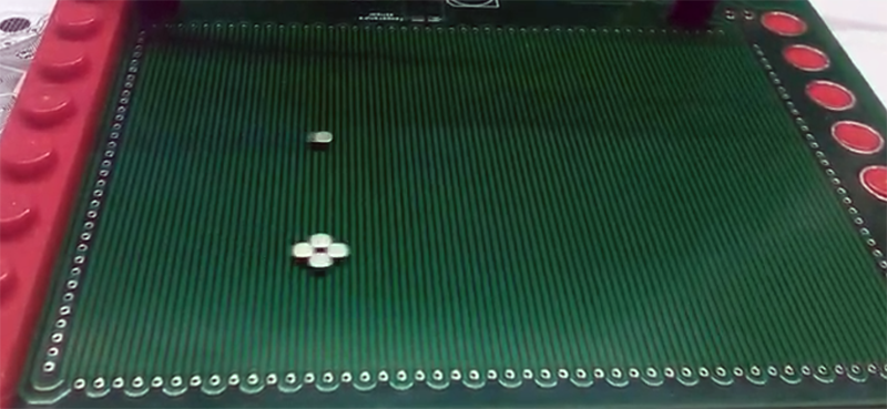
The latest build to show off the possibilities of motors etched on PCBs is [bobricius]’ micro manipulator. It’s a 100 mm square board capable of moving a small magnet around the surface. The point? Well, if you have to ask that question you’re really never going to get the point.
The design of this stepper motor is simply two coils of wire, with the X axis of the grid placed on the top copper layer of the PCB and the Y axis on the bottom copper layer. There are four poles to each of these coils, and they plug right into a standard stepper driver, so to control this board all you need is a basic Arduino and a motor shield. Or a RepRap board, take your pick, you probably have something sitting around in a junk drawer.
In the test of this board, the stepper motor can move small rare earth magnets around quickly and with high repeatability. As for what use this PCB stepper motor has, if you have to ask that question, you’ll never know. Also, because it looks cool.


Very cool! “Back in the day” I worked with a semiconductor wafer prober that was also similar to a splayed-out stepper. Rather than a powdered iron rotor, it was a powdered iron table with a grid, and the wafer stage had the stepper coils embedded in the base. If I recall correctly, it was also part-hovercraft, the stage floated on an air cushion over the table. It was capable of micron precision in X, Y, and Z.
Electroglas EG2001X series.
Still in use today. EG4085’s, and EG4090’s are still used in lots of production test setups and sold refurbished.
We just bought a fully upgraded EG2001CXE at $work for a specialty application.
WOW!! You, sir, are 100% correct. I was playing with those circa 1999-2002 as a product engineer at TriQuint Semiconductor. I’ll never forget that orange.
And the EG2001X was *old* then!
I have a room full of EG4090’s and 4090u’s that I get to rebuild (for the parts I’ve been trained on) every couple of months, as they’re in full-time use. I’ve been curious about the drive system for the chuck. We can pop it loose from the drive and scoot it around the enclosure when rehoming it: once you physically exceed the holding strength, apparently it senses it and turns off the holding electronics, and then you can push the chuck around or rotate it. It’s spectacularly good at fine positioning.
Here is 1D version ;) https://hackaday.io/project/164821-ant-highway-linear-motor-for-micro-cars
I remember many years ago [30+) seeing a high speed multi-color plotter that used a similar setup – fun was when the puck with the pens got ‘lost’ and went zooming across the plotting area at several feet per second.
Dude, I wonder if you just cracked making the 100$ portable braille display.
If you can add a slightly inflatable membrane over the top to keep out dust, then
a) inflate membrane slightly so the braille pins can slide out to the required point
b) slide out the braille points
c) vent the membrane so it deflates and holds everything in place
Can you show this working with 1.5mm magnets?
Do you have a setup to allow magnets in parallel to get fed only one at a time (as in lock the other magnets in place)?
I’d like to see a setup with little guide plates to watch the little braille keyboard pins roll up and down the rows to make a low cost braille display. The membrane idea is for dust control and as a no-power lock mechanism.
If you’ve an interest in braille displays check out https://github.com/hzeller/blisplay
I wonder if you could make a PCB-mounted electromagnet array using tiny iron rods, and circular traces around a hole. Even if it was e.g. an 8-layer board, it would probably still be cheaper than trying to wind coils by hand, especially in bulk.
Hollow surface mount inductors?
Pin through the middle connected to a spring on the rear as a backstop, soldered to the back of pcb
Sort of like a mini solenoid — but you can buy mini solenois cheap too from china etc
PS: If that wont work because inductors cant do that, bear in mind I know little of their operation and need to learn, but you know, spitballing…
I would really like to see a real life jumanji board using this and an oled behind a lense for the smoky text in the center.
This is extremely cool and one of the most unique uses of circuit board hack I have ever seen.
If its capable of micron precision, I was just wondering today if I could make a better Optical centering and measuring lathe tailstock microscope for my Schaublin 102. The swiss versions are hard to find and extremely costly, but only readout to 0.01 mm.
I could get a much more compact package and with the Precision of parallelism limited only by the etching process in a more compact package with higher resolution if something like this can guide a lens Crosshair while standing vertically, as it would sit in use on the tailstock of the lathe.
Definitely interested to see where this goes. If you work in micro precision like a watchmaker this could be very useful in limited circumstances
The electroglas wafer prober we have at work (see first couple of comments) are easily capable of positioning a 50 micron probe tip on a 50 micron bondout pad millions of times in a row. This is not a homebuilt 2d positioner, though: it’s a commercial product. With microstepping, you might see some linearity issues (not all microsteps are the same size) but you should be able to get nearly arbitrary precision.
They use a simmilar approach to bulid a Formula 1 race track in Hamburg for the Miniatur Wunderwelt.
Here are some early tests (in German):
https://youtu.be/bl5jziS66Zk?t=543
On display:
https://youtu.be/7r73FHRAEqY?t=249
Formula 1:
https://youtu.be/dacoglOa5Qc?t=48
Hmm I only really see it moving the magnet in 1 axis. Where can I see 2-axis movement without a helping hand, for example in a circle?
https://youtu.be/A9eIAHiXQ_I moving by hands bout not touch magnet :)
Amazing! Thanks.
Gentlemen, if you are interested in this topic, then you probably will see the following video with pleasure:
https://www.youtube.com/watch?v=7NhEEGoGROg
That video is private.