Here at Hackaday, we thought we’d seen every method of making PCBs: CNC machining, masking and etching with a variety of chemicals, laser engraving, or even the crude but effective method of scratching away the copper with a utility knife. Whatever works is fine with us, really, but there still does seem to be room for improvement in the DIY PCB field. To whit, we present rapid PCB prototyping with electrical discharge machining.
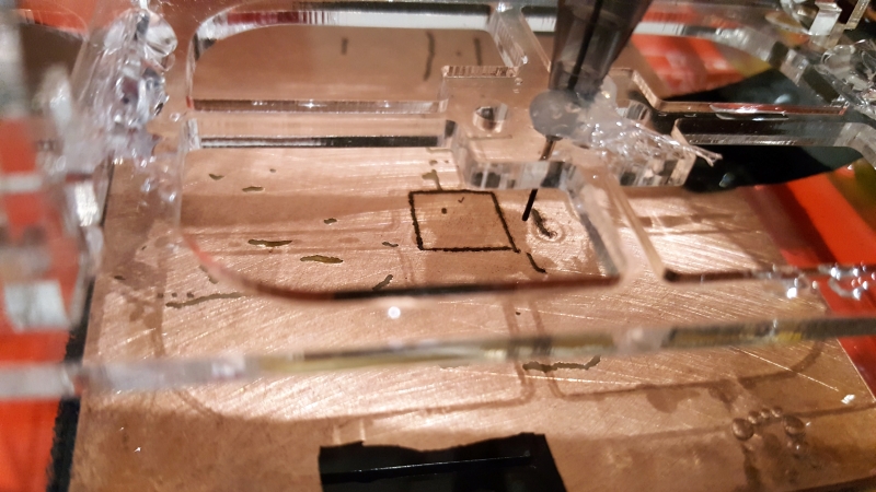
Using an electric arc to selectively ablate the copper cladding on a PCB seems like a great idea. At least that’s how it seemed to [Jake Wachlin] when he realized that the old trick of cutting a sheet of aluminum foil using a nine-volt battery and a pencil lead is really just a form of EDM, and that the layer of copper on a PCB is not a million miles different from foil. A few experiments with a bench power supply and a mechanical pencil lead showed that it’s relatively easy to blast the copper from a blank board, so [Jake] took the next logical step and rigged up an old 3D-printer to move the tool. The video below shows the setup and some early tests; it’s not perfect by a long shot, but it has a lot of promise. If he can control the arc better, this homebrew EDM looks like it could very rapidly produce prototype boards.
[Jake] posted this project in its current state in the hopes of stimulating a discussion and further experimentation. That’s commendable, and we’d really love to see this one move along rapidly. You might start your brainstorming by looking at this somewhat sketchy mains-powered EDM, or look into the whole field in a little more detail.


I’d imagine taking the same precautions as a proper EDM setup would help here. To wit: Submerge the workpiece and tool in a dielectric to control the sparking and reduce the spark gap, controlled tip shape (sharp but ball nosed needle probably) to shape the field as required.
I think the biggest problem is that as disconnected traces start to form they are no longer connected to ground and thus no further discharge to them will happen. Even when starting out distance from the ground connection could affect the shape of the “cut”. I doubt this is an easy problem to solve (or a better solution than a standard PCB mill) but if someone wants to find out I’d say go for it, it’ll certainly be interesting.
On review, I had missed the bubbles, apparently his setup is submerged in a liquid. Given the brightness of the sparks then, I’d say, voltage too high (and as a result too much amperage), frequency too low, gap too big.
EDM isn’t a process for when you’re in a rush. The best result is usually also a lot slower than the fastest option.
It’s first version, there is no frequency (30V DC, limited to 3A). There is no gap, he just mashes electrode into pcb with slight tension. He has results here because he just removes exactly 35um of copper. Still cool technique.
There is supposed to be a gap. As I understand it, EDM normally controls the probe to touch the work and then withdraws it to sustain an arc. Zero current means restrike, a short circuit means withdraw, and the region between is where activity occurs.
Yeah we have run it submerged in water. We actually added a build log after this was written wit some results testing a modulated signal. We have used 30VDC previously, but you are right it is a violent spark. We intend to play around with those inputs since we don’t have EDM experience and it’s surprisingly hard to find information online. If you have suggestions for voltage or signal modulation I’d love to hear it.
I have seen a fair bit of informed info on EDM in general from “tomp” on the LinuxCNC mailing list.
For example, in this thread: https://sourceforge.net/p/emc/mailman/emc-users/thread/200708210833.06084.tomp-tag%40sbcglobal.net/#msg13917245
Other threads on EDM in that archive go in to details of the shape of the discharge voltage curves etc.
The problem of “disconnected traces” can be probably fixed in software, by leaving bridges to be cut last. A PCB milling machine would probably be faster, and could also drill holes for through-hole components, but this approach has potential for very thin and close traces.
a brush, ring shaped around the electrode would sort most of the disconnect issues. I havnt read the article yet but experiments with DC both polarities and high and low frequency AC, to see 8f the arc can be tamed down. also worth trying Tig welding tungsten as it’s readily available, sharpens nice, and has purpose. made holders and collets.
Disconnected traces isn’t a problem if you raster rather than trace.
I guess the optimum solution would be a hybrid raster / engrave approach.
If you trace the tracks like a milling machine or gcode plotter you will indeed isolate copper (though that might be helped by having a circular brush surrounding the electrode to provide the return path).
However, if you scan the pcb in a raster pattern like a laser engraver, one edge of the copper should always be connected to the unetched part and so be able to complete the circuit.
I wondered about this a while ago (but all credit to Jake for actually trying it) and wondered what electrode to use. I think graphite is used in some EDM systems as it burns slowly. Maybe a polymer/graphite lead from a propelling pencil would do ?
Yeah we have proposed rastering across as a possible solution, just not sure how well the cuts will look then, and have not tested it. We do in fact use polymer/graphite lead from a mechanical pencil and it works really well. We have tested down to 0.3mm. It is brittle though.
I briefly played with a doorbell EDM setup ( a la Jerry Ellsworth ). Mechanical pencil graphite has good dimensional stability and conductivity but might be a little soft. The fillers leave a small amount of white ash though. I’m not sure if it is a clay and/or polymer binder. If polymer I was thinking about trying to burn it off by running an excess of current through it before use. I was running it in air, which as I understand it greatly decreases the efficiency of the process. I think some of the powdery swarf might re-weld to the substrate and it tends to sit at the bottom of the hole. I intended to try water and mineral oil to see how much of a difference it makes but I never got around to it. Oil contamination would probably damage the device I wanted a new hole in anyway. A more automated setup might use a spool of fine copper wire as the electrode, something reminiscent of an extruder from a 3D printer.
There is a different form of EDM (wire-edm) where a wire is passed through a drilled hole in the work and then functions as a sacrificial electrode. Since it can’t be passed right through in this case, it’s unsuitable, but I guess you’re suggesting it runs over some sort of pointed guide. That would make for a bigger tip, though.
With flooded EDM, the solution is not static : it’s pumped across the cutting point to wash away the debris, which consists of tiny metal fragments from the work. The same mechanism would remove filler detritus. Some machines use a hollow electrode with the working fluid pumped through it to get right to the cutting site. This wouldn’t be possible with off-the-shelf leads, but it may be that the supplies of tips used on those machines could be a source for a pcb cutter.
Or maybe it is possible with off-the-shelf leads…… ;-)
Supreme Skills! Ultra Small Holes: EDM vs. Drilling: Part 1
https://www.youtube.com/watch?v=pCtWPbTDbuY
I’m not sure the presenter’s blood pressure can handle another episode
I am sure that I considered this idea 10 or more years ago, and equally sure that it wasn’t something that I thought up independently.
Ah, yes, here is discussion from 2006 and a link (apparently dead) to a Yahoo group that was doing it.
https://www.electronicspoint.com/forums/threads/edm-applied-to-make-pcbs.71130/
Yeah we are certainly not responsible with inventing the idea, although we did come up with it independently. I have not yet seen results from anyone else, but if you find any please share so we can learn from other’s work!
Applied Science on Youtube did a video about making an EDM machine recently. He might be willing to point you at available resources.
https://www.youtube.com/watch?v=rpHYBz7ToII
What happens to the vaporized copper? My one thing about milling a PCB is that the fiberglass dust from FR4 boards is not good to breathe, and it floats around in dust. You should really enclose the whole thing and suck out the dust into a cyclone.
Since it’s in a water bath, anyway, I’m guessing it would naturally capture any dust.
Submerge the pcb in some oil or even just pool a bit on top, vegtable oil will do, then mill away
Does the cyclone capture all of the FR4 dust or spread it around the workshop?
I use FR1 instead of FR4 although it isn’t as stiff.
Fiberglass dust is relatively heavy, so it should capture it. That said, I’m also running it from a shop vac with a HEPA filter as the second stage.
There was a design for a pcb milling machine some years ago in Model Engineer’s Workshop magazine which used a vacuum-turbo driven cutter. This made for very high cutter rpm and the air sucked into the impeller was pulled into a vacuum cleaner carrying the dust with it.
It may be that it would be appropriate on EDM too – circulating the fluid using a pump which extracts near the tip and filters before returning the solution to the bath.
Very nice! Keep us posted!
There was a project shared on the RepRap forums a few years ago where someone used EDM to etch PCB’s – might have some useful ideas: https://reprap.org/forum/read.php?1,652457
Perhaps the best g-code method might be to just do all of your isolation cuts in order disregarding their actual electrical connections. I think I would start with all the cuts on one axis first, then do the other axis working end to end.
This way you get the better quality of a vector movement, but the ordering that never breaks electrical contact.
That is a neat idea. Another thing worth trying would be to order the cuts from the those most topologically inside to the outside. Similar to how very detailed scrollsaw work needs support from the outer edges, you work from the most nested shapes outward.
Looking at the formed electrodes used in commercial EDM machines makes me think of the original use of g-code – to move and plot a number of shaped apertures. While these are typically line-widths and holes, custom shapes are also possible. So you could have an electrode for a a T-junction, or an ic package.
Love to see more progress on this idea. Finer cleaner trace and a cheap to operate head unit for 3D printer would be sweeet. Plasma and laser arent cheap.
+1. I would love to have one, but would rather buy it from Inventables or AlephObjects rather than spend ages developing it.
Genious Idea.
Why didn’t I think of this?
EDM seems to make more sense for quick prototyping then milling with very fine mills (and therefore also slow).
AvE (Mr Bumblefuck) has also dropped some hints he’s interested in EDM, and had trouble finding good info for parameters. I believe he’s trying to share info about EDM with his viewers, possibly via Patreon.
Some links to various EDM projects and information
https://groups.yahoo.com/neo/groups/EDMHomeBuilders/info
https://www.cnczone.com/forums/general-waterjet/108757-homebrew-edm-power-supply-question.html
http://www.rroij.com/open-access/study-of-pulsed-dc-power-supply-parametersfor-microedm.php?aid=43980
https://www.homebuiltedmmachines.com/
http://www.reliableedm.com/Complete%20EDM%20Handbook/Complete%20EDM%20Handbook_9.pdf
https://www.youtube.com/watch?v=-a1JEWbnvMo
https://reprap.org/wiki/Electrical_Discharge_Machining