For some of us, there are few sounds more satisfying than the deep resonant “thunk” of a high quality toggle switch slamming into position. There isn’t an overabundance of visceral experiences when working with electronics, so we like to savor them when we get the chance. But of course there’s no accounting for taste, and we suppose there are even situations where a heavy physical switch might not be the best solution. So what do you do?
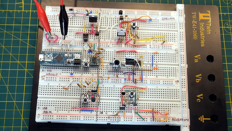
 Enter the latching power circuit, often referred to as a “soft” switch. [Chris Chimienti] has recently put together a fascinating video which walks the viewer through five different circuits which can be used to add one of these so-called soft power switches to your project. Each circuit is explained, diagramed, annotated, and eventually even demonstrated on a physical breadboard. The only thing you’ve got to do is pick which one you like the most.
There’s actually a number of very good reasons to abandon the classic toggle switch for one of these circuits. But the biggest one, somewhat counterintuitively, is cost. Even “cheap” toggle switches are likely to be one of the most expensive components in your bill of materials, especially at low volume. By comparison, the couple of transistors and a handful of passive components it will take to build out one of these latching circuits will only cost you a couple of cents.
Even if you aren’t in the market for a new way to turn off your projects, this roundup of circuits is a fantastic reminder of how powerful discrete components can be. In an age where most projects seem assembled from pre-fabbed modules, it’s occasionally refreshing to get back to basics.


The main goals of any switch is:
1. Be able to handle the amount of current the application needs.
2. Not break from the voltage it will need to isolate.
3. Not waste power.
Most soft switches tends to consume power even when the product is off, making them undesirable in some applications compared to a physical switch. This isn’t though always the case, since one can build soft switches with no standby power consumption.
Though, a physical switch is a very simple device, and tends to have fairly high reliability, even when it comes to more extreme situations. Most switches doesn’t care about a 2 KV spark, while most transistors gives up the magic smoke.
So depending on the application, a transistor might simply be inadequate. Not to mention that a 10 amp rated switch is almost a novelty, while a transistor able to handle the same current is typically not the cheapest of devices.
In the end, I mostly go for mechanical switches due to their overall ease of integration into a larger project.
Though, in some cases a transistorized solution can be more elegant.
“…10 amp rated switch is almost a novelty,”
Your use of “almost a novelty” in this instance is incorrect. A more clear expression of your intended thought might be obtained by using “commonplace and inexpensive” instead.
Well no, he has a point. For instance if you search in Digikey for DC pushbutton switches (AC is not applicable in the examples given, then out of the 4,301 pushbutton switches, only 164 (4%) are rated for 10 A DC, and many of these 164 are listed incorrectly.
But inexpensive is correct. Typically 10A rated switches are more bulky though.
What I am missing from the original comment is
4) not bounce around like crazy. i.e. when you press, generate on/off/on/off/on/off/on spikes.
Yes, Switch bounce is a very important thing in signaling applications.
Less important in switching power supplies, though, excessive contact bounce can lead to contact welding…
Though, most power switches have a clear, strong “click” to them, contact bounce is usually not that big of a problem. Compared to most smaller signal level switches that don’t slam hard into place.
Bouncing switches generate lots of signals… ;-)
Obviously nobody is putting a soft switch on a 2 KV load, this seems like a pretty ridiculous comparison to make.
Meanwhile, the majority of consumer electronics will be using some kind of soft power control. So clearly it’s worth understanding.
I assume the 2kV spark refers to ESD, if so, that’s actually pretty low.
Yes, I were thinking ESD and such. And yes 2KV is very very low in those cases as well…
On typical mains, one should expect to see 2+ KV on a “regular” basis for various reasons.
Sometimes you do want a physical switch. e.g. safety reasons
What happen if you firmware hangs and cannot be shutdown/reboot by switching the device off and on again?
Many times I have to use the recess reset button on my tablet because it got into a weird mode while shutting down and won’t power off.
Having that as a backup is nice, but generally the reset pin of a microcontroller is as good as a power cycle.
Beware: assuming a reset is the same as a power cycle WILL some day bite you in the ar$e, and bite you hard.
Mercury switches. Reed-relays.
For anything powered by rechargable batteries, the protection circuits and self discharge will be ten times more than a good soft switch. BJTs aren’t the lowest power things out there, but the just letting the microcontroller handle on/off can easily get you into the sub uA range.
The one thing I will say in favor of hard switches. It’s really annoying to have a soft switched device that can’t come back by itself when power is restored. Look at common power banks, and how basically none of them can be used as UPSes for that(And other) reasons.
A hard switch is nice because it’s behavior is predictible. Soft switches can do this almost as well(With always-on microcontrollers and batteries they often have anyway), but the behavior is rarely documented.
I disagree with your assessment for the main goals of any switch. The main goal should be to alter the behavior of the circuit it’s a part of. It seems like you’re implying in your third point that the goal of having a switch is to not waste power, but that’s rarely the case, especially now that switches most often just signal to a microcontroller rather than physically turn on components. There are exceptions to this, mostly power switches and switches in some high-power applications where it’s useful to have a high-power switch rather than a switch and high-power transistors or relays.
As for the rest of what you said, I think that the low power consumption of soft latching circuits is usually acceptable, but for very low and high-power circuits a physical switch is best.
Thanks for your time, I hope you’re having a good day.
I generally refer to switching mains. (And/or lower voltage DC supplies.)
In these cases, having a switch that wastes power while off, is generally not desired. (Or consume excessive amounts of power while on.)
Signal switching is a totally different story. (Though, I don’t really see much of a reason to have a complicated soft latching circuit for toggling a pin on a micro, seems strange…)
Cool video, I’ve looked into circuits like this but have yet to implement any of them. I’m working on a device that I’ll need to turn on manually, it’ll do it’s thing and then turn itself off. I’m thinking a momentary switch and a pin from the micro attached to the enable pin on a voltage regulator might work – the switch will enable the regulator, power the micro, which will then hold the pin high. The micro can then pull the pin low when it’s done doing it’s thing, and something like a 1 meg pull down on the pin will make sure the regulator enable pin stays low. Have to verify, but it seems simpler than using multiple mosfets, but not having to manually turn it off helps simplify it.
Have a look at the end of this article : https://connect.ed-diamond.com/Hackable/HK-012/Nos-amis-les-MOSFET
The regulator will consume constantly (even when it’s off), since it’s not made for this task, it does not show a huge impedance. That’s why all those circuits use a MOSFET upfront to present a large impedance to the input power source. You can sort this out with a MOSFET + regulator EN pin, but you’ll still need an additional pin to turn of your MOSFET (so you end up with 2 pins used on your microcontroller).
@sweethack: Most of the regulators with enable pin goes down to ~1uA (or less) when they are in sleep mode. Both linear regulator/LDO or buck converter have their MOSFET in series connections, so they don’t need to to have an external MOSFET. There are boost converter with internal cut-off.
As for GPIO. The circuit by [Chris Chimienti] I believe uses the same GPIO for sensing and control. IT’ll be a matter of figuring a way to do something similar if you wish.
Yea, the regulator I’ve been for previous versions of my board specifies a max shutdown current of 1.5ua. Powered by a 50mah+ lipo should last years in shutdown mode. But it’s a good point which I’ll keep in mind and always check the shutdown current of regulators if/when I use them in this way.
I have a uC project with RTC that draws about 2uA when “off”. The 100mAH LiPo voltage hardly moved after a few months. That’s with unknown quality Chinese LiPo taken off a board.
Lithium chemistry gives really flat discharge curves, so a LiPo battery could be half-discharged without showing much of a voltage drop. Drawing 2 uA it would take 50,000 hours to drain a 0.1 AH source. That’s theoretically a bit less than 6 years to fully discharge the battery.
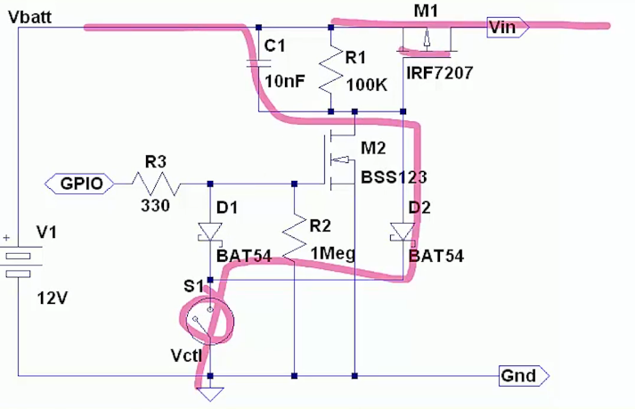
The node at the switch can be 12V, so I would be careful about (reverse) leakage current for schottky diode D1 by either using a lower value for R2 (say 330K) or substituting a silicon switching diode. Schottky diode goes up in elevated temperature.
Watchdog, preferably external.
Ok so how to integrate into 3D printers and the like
I’m confused by circuit #2. caps don’t pass DC current, so in the initially off state- the p-channel gate is pulled high via the 100k pullup. pushing the button shouldn’t change that? Maybe if the 1uF was a resistor (10k to ground on a button push)?
I think it is acting like a charge pump. Both sides of the 1uF cap will be at 5V, so it isn’t holding any charge, then when you press the button, the 10k side will go low and the 100k side will start charging the capacitor. That’s going to pull the 0.1uF cap down before the 100k can charge the 1uF cap.
Assuming the 1u and 10uF capacitors are at 0V, pressing the button will pull the other side of the 1uF capacitor at the PMOS input to .5V (90% to 0V because of the .1uF), then will begin charge up with a 100ms time constant. When the PMOS turns on, the 10uF has 0V so the NMOS is pulled to 5V with a 3S time constant. If the button is released, then the 10uF is discharged to 0V and NMOS pulled to 5V via the 100K+300K. Either the button press or GPIO held low will eventually turn off the NMOS after the 10uF charges up with the 3s time constant. The 1uF keeps the long button press from keeping the PMOS on as in other circuits.
I have no idea why the test circuit wouldn’t work. Button bounce shouldn’t matter. I wonder what the voltage is at the NMOS input.
On the final circuit, remove the 100K pullup resistor to 9V on the input pin. Use the internal pullup resistor instead. This will keep the voltage on that pin from going above the Arduino voltage, and simplify the design.
I really like the “slick” one requiring just one GPIO pin. Is it possible to do the same thing by turning the latching circuit on by pulling it high, instead of low? I’m using three push buttons using an analog input to determine which button was pressed and then carry-out the appropriate steps in my firmware. It would be really nice to be able to pull it high to turn it on and use my firmware to determine which button was pressed for an appropriate amount of time (i.e. 3 seconds) as long as it was the correct button. I good with microcontrollers, get by with circuits, but coming up with something that could make that work is at a level I haven’t reached yet. I’d hate to have to add an additional button if I can help it.
Tom, think I figured out why Circuit #2 doesn’t work for you but can’t explain why. I purchased parts for Circuit #2 before I read that you were unable to get it to work. Anyway, I put it on a breadboard and I have used N-Channel MOFETs plenty of times before and have a basic understanding of how they are supposed to be used. I ended up using a BS107P N-Channel because I’m running off a single Li-Ion cell. I looked up the datasheets to make sure I was connecting the Source, Drain & Gate pins properly. When done I tried it but, like you said it didn’t work. So, not having use P-Channel MOSFETs before, I flipped it around the other way, nothing at all that time so I flipped it back around. Well, thought maybe I might have read the datasheet wrong for the N-Channel MOSFET, so flipped that around instead. (Works when N-Channel MOSFET is connected with the Drain pin towards Ground) Then the system worked as advertised, mostly.
It does everything that I would like it to do, I turns my system on, turns if off and in the case of an issue, holding down the push button for around 3-5 seconds does force the system off like it’s supposed to. However, it seems like some times, the system turns on automatically, for no apparent reason. It doesn’t happen very often but it does happen. As soon as I can find a solution to prevent this, I’ll be incorporating this into other projects. I decided that it would be easier to add another button than search endlessly for what I was looking for earlier.
If someone has the time and could verify this – maybe explain why it works this way. From what I know it shouldn’t work, right?