There was a time when high voltage in electronic devices was commonplace, and projects driving some form of vacuum or ionisation tube simply had to make use of a mains transformer from a handy tube radio or similar. In 2019 we don’t often have the need for more than a few volts, so when a Geiger–Müller tube needs a bit of juice, we’re stumped. [David Christensen] approached this problem by creating his own inverter, which can produce up to 1 kV from a 12 V supply.
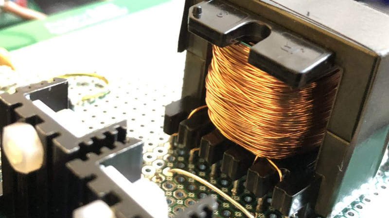
Instead of opting for a flyback supply he’s taken a traditional step-up approach, winding his own transformer on a ferrite core. It has a centre-tapped primary which he drives in push-pull with a couple of MOSFETS, and on its secondary is a voltage multiplier chain. The MOSFETs take their drive at between 25 kHz and 50 kHz from a 555 timer circuit, and there is no feedback circuit.
It’s fair to say that this is a somewhat hair-raising circuit, particularly as he claims that it is capable of delivering that 1 kV at 20 W. It’s usual for high-voltage supplies driving very high impedance loads to incorporate a set of high-value resistors on their outputs to increase their internal impedance such that their danger is reduced. We’d thus exercise extreme care around this device, though we can see a lot of value in his description of the transformer winding.
We can’t criticise this circuit too much though, because some of us have been known to produce far hackier high voltage PSUs.


1.21 jiggawatts?!? What were you thinking?!?
Correct me, but chopping up the primary side of a high-ratio transformer is *exactly* what a flyback supply does.
He’s getting 150 volts on the secondary of the transformer. The rest of the voltage is from the capacitor/diode C/W charge pump. You’re right about the theory, but I think what he meant was difference between a controlled voltage from a transformer based on primary to secondary turns ratio vs the counter emf spike created by collapsing magnetic field.
Well, no. In a flyback current doesn’t flow in the both the primary and secondary at the same time – the secondary diode prevents that. A flyback is essentially a boost converter with a second winding on the inductor, it stores energy in the core. This is why you can get higher voltages than the turns ratio would indicate. For example, getting 300V form 5V with a 1:10 flyback.
The one described here is a push pull. So the output is pretty much down to the input (x2) and the turns ratio.
that’s what transformers do, fly back transformers are not iron core so more efficient at the higher frequencies.
No, in a typical transformer, current flows in both the primary and secondary at the same time. For a forward converter, push pull, half bridge, or your standard 50/60Hz AC etc.. In a flyback, the transformer is really a coupled inductor.
This is why flyback transformer cores are typically gapped to increase the amount of energy it can store per cycle.
You’re right in that an iron core isn’t for high frequency, but ferrite is used for applications other than flyback – look at a typical ATX power supply.
So, I wrote the article… the difference is, that a flyback supply stores energy in the air gap of the core. In fact, a flyback transformer is more accurately a coupled inductor.
The high voltage of the flyback is derived from the back EMF, that flows when the primary is no longer conducting. This causes a large voltage spike on the secondary. The secondary wants to maintain current flow, and “spikes” the energy that is stored in the shared magnetic core. This means, that the primary side isn’t conducting /always/, and that you therefore need only one switch.
In this supply, the primary side is conducting in two directions from the center tap. This means that it is acting like more of a standard step-up transformer, á lá AC linear transformer. The alternative to this would have been to use an H-bridge, to act as a full four-switch push pull, maintaining conducting in two directions across the primary winding. The center tapped idea, however, allows you to drop down to two switches as the cost of a small bit of magnet wire. That’s why I went with that.
This had a few advantages here, including the fact that the back EMF (i.e. the high voltage spike) is quite unpredictable, especially when you are winding your own transformers. The primary-secondary side capacitance plays a role; as does the ESR of both, as well as the core material.
So in short, it’s the difference between storing energy in a magnetic core and letting it out by stopping conduction on the primary, causing a HV spike… or using a transformer with a fixed, known step-up ratio defined by the turns ratio.
I hope that makes sense! If not, I’d love to source some better explanations than I am capable of :-)
/David
Well it was much better than my explanation! Thanks for writing dude.
Yep, that’s a good description.
Flyback works by allowing current to flow into the primary of a coupled inductor, then switching it hard off. This causes the voltage across the switch to rise well above the supply voltage (12V in perhaps screaming up to 300V). The switch is only saved by allowing the energy to flow somewhere – and that’s where the secondary comes in. Once it starts conducting, it allows the energy to bleed away and saves the witch on the input side from too high a spike. A 100x ratio delivers 30kV in this example. This is exactly how classic car ignition systems work too. The difference between a flyback and car ignition is a winding in the flyback that drives the gate of a semiconductor – whereas ignition systems are triggered in time with the engine by a rotating breaker.
It’s entirely possible to have less turns on the output than there are on the input. Then the flyback could act as an isolated buck converter. But generally the ratio is high and so it has a boost function. They’re complex and require witchcraft to get right, so I have generally gone for hard switching H-bridge designs and conventional transformers. Or swipe a working flyback from something and purpose it.
Firm favourite source of inexpensive flybacks are plasma balls. They even come with a handy 12V supply. The ones I’ve found are usually about 15kV and 35kHz. Fun to run into a voltage multiplier and generate threatening sparks. Also means ending up with surplus glass balls filled with easy to ionise gas. They don’t last long in the microwave but are quite fun for the first 1 or 2 seconds.
Good work winding your own transformer.
> This is exactly how classic car ignition systems work too.
> ignition systems are triggered in time with the engine by a rotating breaker.
Not quite. The classic ignition system was the magneto ignition, which had a magnet that swept over a coil to induce a current (or a piece of iron swept through a gap in a magnetized core), and then a switch that cut off the current to generate the voltage spike right afterwards.
It’s still used in motorcycles and the like, because it’s light and reliable. Hard to start though.
Really nice project. I’d kind of like to see the HV bits elevated above the perfboard solder pads or on a separate insulator to give a little more insulation gap. The close spacing of the solder pads makes me a little nervous for your safety. HV can jump distances in high humidity. Good job though.
Oh, and a small note. The fact that it can deliver up to 20W certainly does mean it’s dangerous, but… even a flyback supply will typically have an output reservoir capacitor. This can deliver much more current than the supply proper for a short amount of time.
The idea here is basically to maintain a lower output impedance, to make sure the voltage doesn’t start to drop off when loaded. This means any devices powered (such a GM tube, IIT etc.) won’t have output rail sag and re-charge transients overlaid on their output. You’d have current limiting resistors in the circuit anyway.
Additionally, when doing nothing, the supply dissipates around 0.4W. Hardly enough to be visible in thermal imaging (which I didn’t include for that very reason). It simply rises to meet the demand, as it occurs, up to around ~15-17mA for the highest voltage output, at which point it will start to drop. If you wanted a “safer” lower-power supply, you would drop down the multiplier capacitors to maybe 1nF, or even as low as 330pF…
Nice build, [David]!
I’ll agree that 20W is potentially dangerous at 1kv, but it’s not that unusual for those of us used to working with higher voltages (as I suspect that you are). I have a variable power supply I built that can produce up to 2kv DC at up to a whopping 500 watts! It’s used primarily for testing large, high voltage capacitors for leakage. I suppose that it could be a bit less of a beast, but it was built from what pieces I had lying around, primarily a very heavy Bendix 1300V 0.48A step-up transformer.
Needless to say, I am VERY cautious when using it!
“Hair-raising” requires DC voltages far higher than 1kV to achieve electrostatic repulsion. A Van de Graaff generator, for example, will do the trick, but not this thing.
Doh. CCFL inverters for the win!
I do a lot of toying around with particles in vacuum (hobby). You often need HV to run anything from a low current ionization source to a photomultiplier tube to a geiger counter. When it became apparent that the CRT was going away – and even CCFL backlights, I stocked up on all the HV parts I could find, and I’m glad I did…I think you can still find most of them if you look, but pickings are getting slim, particularly for the diodes you need for an ultrasonic inverter that runs at a kv of output – before you get going with Cockroft-Walton.
CCFLs are very “stiff” in that if you skip the tiny output coupling cap (used as a ballast in the original application) you can reasonably well regulate the output by using an lm317 and pot on the input – just feedforward. The 12v input ones will most often run down to 1.5v or so (and put out lower voltage there, but that’s the point).
The HF makes the output a lot easier to filter with just cheap old ceramic capacitors, as well.
Repurpose a mosquito bat.
Noooo, they’re for adding much larger capacitors to and making flies disappear :O)
Hurts quite a bit more when you poke it though :O(
Was anybody else like 6 years old and put together a RS goofy light kit? Not even a 555. That was the primary side of this only more elegant. And FWIW I have real doubts about the power output of this device. Voltage doublets are notoriously low current devices. In fact the leakage of a filter cap may self limit the output voltage of the thing. I was hoping for something at least a bit either simpler or more creative. I mean if you are going to be using it with a GM tube and you wanna do more than drive a speaker or a meter, and there is a lot of really simple and time proven art for doing that, you are going to interface it to a micro. Now using the micro and a switching element to drive the transformer and a suitable voltage divider to interface the HV output back t the micro so you actually have closed loop control may have been interesting.
Could’ve made it a simple multivibrator. Or a combined integrator-schmitt trigger with a single op amp. In fact, could’ve made the operational amplifier a matched differential pair.
Dunno if that that would’ve more satisfactory. But 555’s are popular among makers, and although I use JFETs and other things in other projects, the focus here was really just on the inversion. Sorry for not ringing your bells with an interesting relaxation oscillator :-)
By the way, voltage multipliers ARE low current, generally. However, we do have a friend in the formula for reactive capacitance,
Xc = 1/(2π*f*C).
Plotting in our value, 10nF, and ignoring the diode loss (it’s small), we get a capacitive reactance of around 162 ohm. In other words, with a 100V differential across it, we get a peak current of 0.6A. In other words, 600 milliamps.
If you used the same multiplier capacitor size with 50/60 Hz mains – as I write in the article – the current would be much, much lower. So here, the multiplier isn’t actually what is limiting the current.
What is limiting the current is the relatively high inductance of both primary and secondary. Inductive reactance being given by 2π*f*L (not ^-1 as with the capacitance), this limits the current at our switching frequency of ~50KHz; even when the secondary side is loaded.
So I would say that when you did a bit deeper, and actually do calculate the reactances of the seoncdary side, you’ll see that the output current does in fact make very much sense.
Hope that cleared that up-
/David
Show me the output voltage with all 3 stages engaged into a modest load, not open circuit into a dvm.
I could have done it with a NE555.
Oh wait….
Nice project. I have a surplus SW tube transmitter that i hope to put on-air some year, and it needs about 500vDC at up to 25 W. I’ve already collected some 20v to 300v 60Hz transformers; would this project’s drive circuit be up to driving my transformer at a lower frequency?
Any experience/advice with using the transformers from old PC supplies or battery chargers?
Nothing new! try the ghost field directed reflection with zero mass. No need for a transistor opening up unlimited forward current. The way forward is plasmanoid current. The current values for ohms law is to restrictive try monopole electron field coupling.