KiCAD has a rightfully earned image problem regarding beginners. The shiny new version 5 has improved things (and we’re very excited for v6!) but the tool is a bit obtuse even when coming from a electronics design background, so we’re always excited to see new learning material. [Mike Watts] is the latest to join the esteemed group of people willing to export their knowledge with his KiCAD tutorial series on GitHub that takes the aspiring user from schematic through fab and assembly.
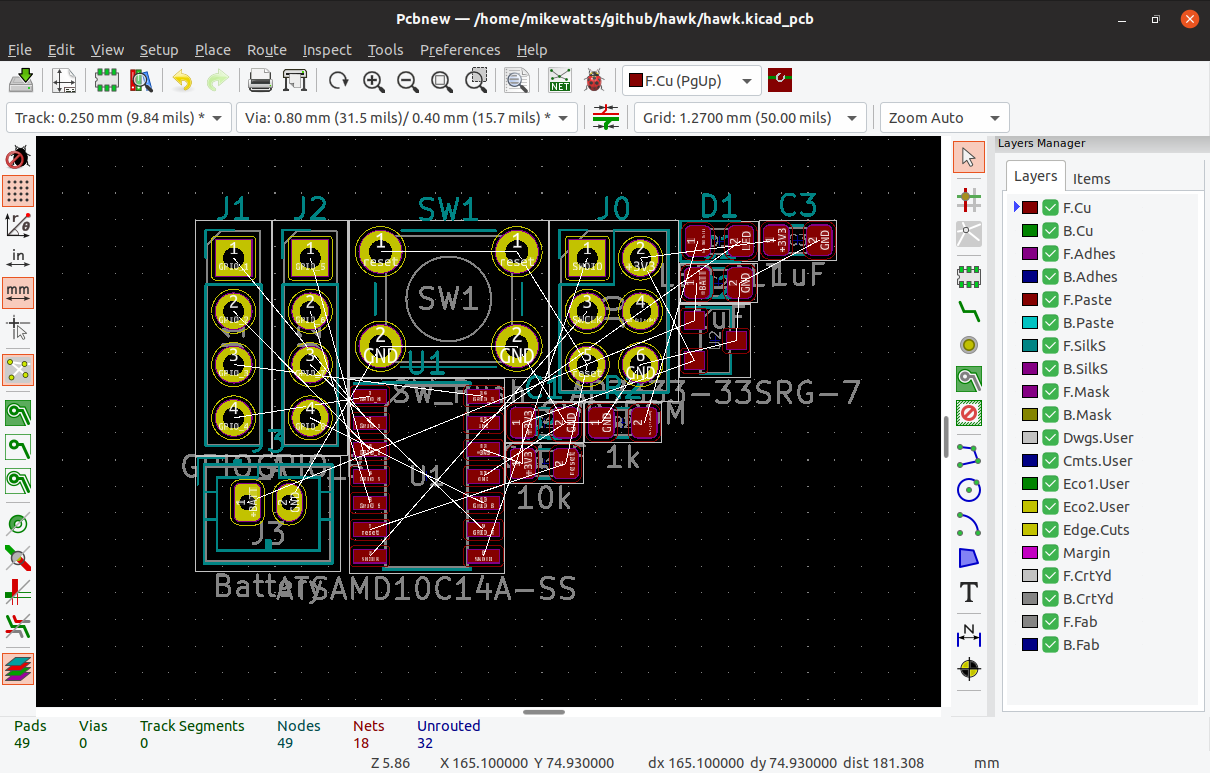
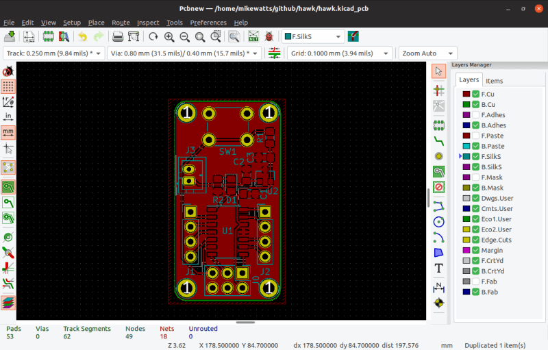
The tutorial is focused around the process of creating a development board for the dimuitive Microchip née Atmel ATSAMD10 Cortex M0 ARM CPU. It opens by asking the reader to create a schematic and proceeds to teach by directing them to perform certain actions then explaining what’s going on and which shortcuts can accelerate things. This method continues through layout, manufacturing, and assembly.
Of note is that when defining the board outline [Mike] describes how to use OpenSCAD to parametrically define it; a neat micro-tutorial on using the two great tools to compliment each other. We also love that upon successful completion of the tutorial series the user will have developed a tiny but useful development board that can be assembled for about $3 in single quantities!
As with all open source work, if you have quibbles or want to contribute open a pull request and give [Mike] a hand!


Note you don’t actually have to make circles in the edge cuts layer for the screw holes, the plated or unplated hole footprints (that were added in the Silkscreen step) are sufficient, as far as I’ve ever experienced.
True! I much prefer to drop in holes as footprints, though it’s annoying to have to recreate them in the mechanical model (one more place for me to screw up the measurements).
No mention of a MAJOR redeeming quality of this tutorial?
The fact that it’s NOT in video format is (sadly) important to mention.
To each their own. I prefer a non-video format.
I understand that many do prefer videos but these days you are all served well enough 1,000s of times over by what is already out there on the Internet. Youtube alone should keep you busy well beyond your natural lifespan.
Let us who prefer something we can use without the audio turned on, take in at the speed we read (much faster than speech for many) and “fast forward / rewind” with a simple up/down eye movement or maybe touch of the scrollbar have this one. It’s our turn.
I guess you missed the fact that i liked the format as well…
I guess so. I was a little confused what you meant actually. Oh well, I got to bitch about how video is taking over all the howtos.
I also prefer non-video format
Sadly? I’m thankful since everyone and their grandmother + dog seems focused on making painfully mediocre video tutorials just so it can be put on YouTube for harvesting views.
chris gammels ‘getting to blinky’ series on kicad is probably the most concise technical video tutorial of all time
https://contextualelectronics.com/courses/getting-to-blinky/
he circuit is simple, but he hits all the basics of kicad in such a short runtime, it’s the model of how everyone should make a video tutorial.
Yes – YouTube has its place, but often it is just an addictive Ego-driven drug habit.
Yet another thing telling me how to work instead of adapting to the way I work.
Workflow tutorials are nice to people switching to the program for the first time, even if they already know broadly how to do the work. Every program has it’s differences in workflow, even if the workflow itself is similar.
After you are used to the workflow, tool specific guides are way better, tho.
It’s a written tutorial, how do you envision it adapting to the way you work? ;)
As someone who’s learned KiCad on my own, without any electrical engineering background, I’m sure there are deficiencies and inefficiencies in my workflow. I’m always glad to see tutorials so I can pick up little things I was doing wrong or less optimally.
Do you expect every single tutorial writer to ask you, personally, how you work and cater their tutorials to you? Christ.
Hymel and Gammel have taught me a lot about Kicad. But I’d like to add a big +1 to the love for the “non-video” tutorial. Well-chosen pictures and text can be a much more efficient way of conveying information than videos, especially if you need to glance back and check some information from earlier in the piece.
But Eagle was also a right pain to learn, decades ago. Having been forced to adopt its methods, they now seem semi-natural to me. That said, a lengthy tutorial can be obfuscating because it only answers a predefined set of assumed questions. Much, MUCH, better would be a manual which succinctly explains how to perform discrete operations – to begin with: How to define a board outline from the tool’s command line, with just and X and a Y dimension, from zero. (No, I don’t want to have to learn OpenSCAD as well.) Then how to grab a side with the cursor, and move it to a new position. If yet another GUI tool has to be mastered in order to define a board layout, then I’ll wait for the manual which describes the data format, so that I can define and edit the board outline with Vim.
But CP/M was also a right pain to learn, decades ago. Having been forced to adopt it’s methods they now seem semi-natural to me.
See what that sounds like? Yes, I too do not want to re-learn everything from scratch year after year just based on some brain-dead assertion that newer is necessarily better but at the same time it is no good to hang onto the same old tools.
” If yet another GUI tool has to be mastered in order to define a board layout, then I’ll wait for the manual which describes the data format, so that I can define and edit the board outline with Vim.”
Ewww, Vim? Learn Emacs dude! Seriously though if you even slightly mean what you are saying then you SHOULD go learn OpenSCAD. OpenSCAD is not a GUI tool. It’s more of a language. Designing in OpenSCAD means writing code. That makes it great for parametric stuff (probably not a PCB design concern) but it also means that for someone who would write directly to a data format.. it’s even better because you can re-use that knowledge for unrelated projects.
If you are just saying you don’t want to go through all that just to define the board layout.. that’s good too. Just don’t use this tutorial. KiCAD works just fine without OpenSCAD.
Ok, I haven’t read it yet to see WHY they are using OpenSCAD. As a pretty heavy OpenSCAD user myself I see the fact that I might be able to leverage my OpenSCAD knowledge to improve my PCBs as a good reason to add this tutorial to my reading list. I look forward to learning what they gain from involving OpenSCAD.
But you don’t need it. You can define all the board layouts you want in KiCAD using only KiCAD so that should not be a reason to not use KiCAD.
‘Designing in OPENSCAD means writing in code’….and that folks is why no one in actual industry uses it. When you are a programmer, it is natural to seek out a programming interface (for everything). I just don’t see it catching on for anyone who wasn’t an EE/CS person to start.
Ok. So?
There are a LOT of us programmers out there and now we have 3d printers and sometimes even CNC routers in our homes and hackerspaces. So what do we care if industry doesn’t use it?
I have read that part of the tutorial now. And I wonder, how easy using one of those point and click GUI tools is it to make those 4 rounded corners, each the exact same size and radius so that the whole thing is perfectly symmetrical?
That sort of thing.. getting EXACT dimensions, to the ability of your equipment to produce the part.. PARAMETRIC DESIGN!
I’m pretty ignorant about what one can do with a GUI CAD tool but I’ll have to see it with my own eyes before I believe they can easily be done by clicking and dragging a mouse!
Actually.. just how natural does it come to any designer, programmer or not to design a 3-dimensional object using a mouse that only moves in two all while viewing the thing on a 2d screen? I’m sure people get good at that but don’t tell me it comes any more naturally than coding. At least with code I can represent x-number of dimensions mathematically and the equations are perfectly readable on the flat screen.
Also, I can certainly imagine, given the right configurator frontend that a lot of non-programmers might customize then print someone else’s OpenSCAD design without ever learning OpenSCAD themselves.
You should check out Fusion 360. Parametric cad is definitely more practical than coding. Especially for parts with non trivial complexity.
Friends, let’s face reality: NOBODY has only a single tool in their toolbox. OpenSCAD is just one more tool among many. Yes, it is generally my go-to for 3d modelling, but that is only because my needs are few and fairly simple. While I doubt that I would ever use it for something complicated, I don’t think that any other software could do things like be given a template and a list of names & job titles and spit out hundreds of customized door plaque STL’s automatically. (There is a good reason that Thingiverse uses its ‘Customizer’ for the site.)
Some workflows I’ve come up with using it in conjunction with other software:
– Trace a bitmap in Inkscape, then export (using a plugin) the result as an .scad file, to be extruded as part of a larger project and everything exported as an STL. I used the same workflow to generate extruded game pieces from silhouette images.
– Code graphics for a project, then export the resulting PNG.
– Generate multiple versions and combinations of guns/turrets/hulls/etc. for a game.
– Generate complicated fence models for another person’s project.
Yes, I could have used other software packages and methods for these, but OpenSCAD did them quickly and easily, and making changes is both trivial and reversible, especially considering you can inject variable changes (including whole Customizer parameter sets.)
In the end, it is an excellent tool to have in your arsenal, but it shouldn’t be the only one.
No one who uses any of the major cad packages fiddles with the mouse to get exact dimensions. They use the tools to drop the right shape/feature roughly where you want it and then then define a relationship to other features and finally define the dimensions by inputting them with the keyboard number pad. Admittedly it takes a bit of practice before you can become fast, but being able to see the part as you create it is a fair bit easier, in my opinion, than knowing all of the dimensions and feature placement beforehand. Sometimes in a complicated assembly you might not even know what a new component part will look like when you begin, so it sortof grows into what you need as you go.
Have you seen actual CADs used in the industry? Especially the super-expensive niche CADs, like PDMS – it’s all in code, with very little GUI being actually used.
Did you really just call OpenSCAD a “GUI tool”?
The OpenSCAD stuff is entirely optional and admittedly a bit odd – I used it in a previous project so I could make a 3D printed case that lined up with the board. I thought it would be interesting to add it to the tutorial I was writing.
Many thanks, Mike, for the extra detail. I’ve bookmarked the tutorial for when I finally move away from Eagle, much encouraged that the board outline can be defined in Kicad. Makes sense to import it though, if you’ve used a CAD package for the case – around an outline of the board. (And a text based tool bears looking at – but don’t tell the others commenting on this thread. ;-)
That Kicad can import an Eagle library or board is a big incentive to give it a go. Just have to finish another project first – a rural off-grid biomass-heated home/workshop with room for my lathe and milling machine. All 8 drawings for planning and building approvals were done in Postscript, as I couldn’t get GUI drawing packages to work. (So no stranger to text-based graphics.) In the end, building up a library of macros for walls, windows, doors, etc. made the job of drawing programatically quite entertaining. (30 years as a programmer quietly leaves its mark.)
After joining a company and been working with Altium, I found that the way Altium organizes their guides is rather nice. I know the steps to create a schematic and a PCB, I just want to know how to execute these steps with their tool, and they have guides describing how to use each function of the program. They have workflow tutorials too. These are nice to understand the workflow of the program the first time you use it.
Now, I’m not saying that Altium is excellent in every tool. Personally, I prefer the way shortcuts work on KiCAD, took a while to learn them, but they are very nice. Altium, on the other hand, has lots of other tools that are nice.
I hope to learn as much I can from Altium so I can remember the good parts and maybe help implementing these parts in KiCAD in the future, if I can.
Been a while since I used KiCAD, though. I need to get back to my personal projects and test v5.
Altium has positive points‽ That’s hardly surprising. For the price they should be great!
Actually.. for the price they should just do all your work for you. While you wait they can even send your choice of girl/guy/other to “keep you company”.
The everything should be free generation strikes again…
LOL
I bet I’m older than you think I am.
So tell me. How do you make a software package that is SOOOO much better than KiCAD that I am willing to pay $4,000 for the difference? And you say I’m the one demanding something for nothing! I didn’t demand that KiCAD release it’s product for free. JP had the freedom to release or not release it under any license he wanted.
Besides, I lived through the days first when only well monied companies could afford compilers. Us kids [as I was at the time] had to make do with BASIC knowing that there would NEVER be anything more than a niche audience for our interpreted code. Then EDA tools came along and it was the same story, big price tags meant to sell to a handful of corporations what 10,000 hobbyists would have bought if they could.
That was not a good way to build up a new generation of programmers and engineers and it shows in how “my generation” turned out. Open Source Hardware and Software have already done far more to build a better world.
When we’re talking about the core technologies that make sustaining modern society possible, yes, they probably should be free. Hoarding knowledge hurts more people than it helps. Viva la open source.
Altium/Protel is fantastic. 20 year old Protel99 is copied everywhere in China because it works – and libs and new parts are easy to add. I do wonder if it is all copied from a single license key :-) If you check the proto PCB houses, they all default to Protel file extensions when submitting a board.
KICAD was the most intuitive tool for me to learn when I started with PCBs. I found all the others way more confusing!
Same with me, although I’d have to acknowledge that I probably learned a bit with each tool so by the time I gave KiCad a go, I was a fair bit over the initial learning curve. But even with that, KiCad seemed to be quick to learn vs. others. Don’t know why, but I found Eagle consistent frustrating.
KiCad has a bunch of problems that make it just short of an excellent tool. They can be fixed, and should be fixed. And yes, I’m trying to contribute to that, not just complain.
A lot of the problem comes from the fact that it’s actually four or five independent tools that came together under one banner, and are only slowly being integrated together. This explains why the shortcuts and interfaces vary between schematic and layout, and why part searching/footprint association is so painful at times. Other problems stem from the original program design, and are apparently difficult to fix – this includes the awful plotter fonts and inability to have nice polylines that stay together when you move them. Some missing things are just puzzling though, like why you can’t do quick moves to coordinates ala eagle while drawing lines or moving things.
Oh man. But I totally chose my EDA tools by their fonts!
Nobody chooses a CAD tool for fonts, but it’s a problem if you’re in industry. When was the last time you saw a quality schematic that looked like they’d used Comic Sans fonts? Would YOU trust products from a company that couldn’t produce good-looking schematics?
Are you kidding? This is 2019! If it doesn’t look like it was tumbled back and forth between English and the various forms of Chinese in an automated translation tool a couple of dozen times I am ecstatic!
This is an awesome resource and tutorial! I love the format and the fact that it is written in markdown and on Github. I hate video tutorials. written ones are much better (for me anyways) ! Thanks for sharing this. I plan to post my own written KiCAD tutorial in the future as well.
Great tutorial. Thanks for sharing!
The tutorial referred to is terrible. It starts someone off by using labels instead of wires. A newcomer will find this “disconnect” difficult to follow. You start to learn about basic electronics with schematic diagrams that include WIRES. If you want to use labels to go off board or to another circuit page, fine. You can learn how to do this later. But don’t start a tutorial with just labels. It’s a poor teaching technique for this type of design software.
Nope, sorry, you’re wrong. Using labels like this simplified the schematic. Wires are fine when you have a small number of components to connect, but as soon as there are more than a few, wires crossing all over the place are confusing and error prone. Thoughtfully named labels (sure, I used global labels but that’s because I find them easier to read) make a schematic manageable and MUCH easier to reconfigure things later – as I do in a later step to reassign the position of the GPIO pins.
In this project, the schematic is really only a vehicle for laying out the PCB which is plenty wires.
It’s worth pointing out too that I didn’t come to these conclusions all by myself – I’m certainly no authority on any of this stuff, merely sharing what works for me but I learnt by looking at what other people do and this is broadly what I see…