The Coanda effect is an aerodynamic principle regarding the way fluids tend to flow along curved surfaces. This can be used to direct a flow, and [Tom Stanton] wanted to try out its application on a quadcopter. (Video embedded below.)
The project began by firing up the 3D printer, which made experimenting with a variety of different aerodynamic forms easy. Wishing to avoid simply putting a large obstruction in the way of an otherwise efficient propeller, the experiment first used impellers to direct flow sideways, over the edge of the Coanda domes. The impellers, combined with the Coanda domes, were a factor of 5 less efficient at generating thrust compared to a standard prop setup, but [Tom] persevered.
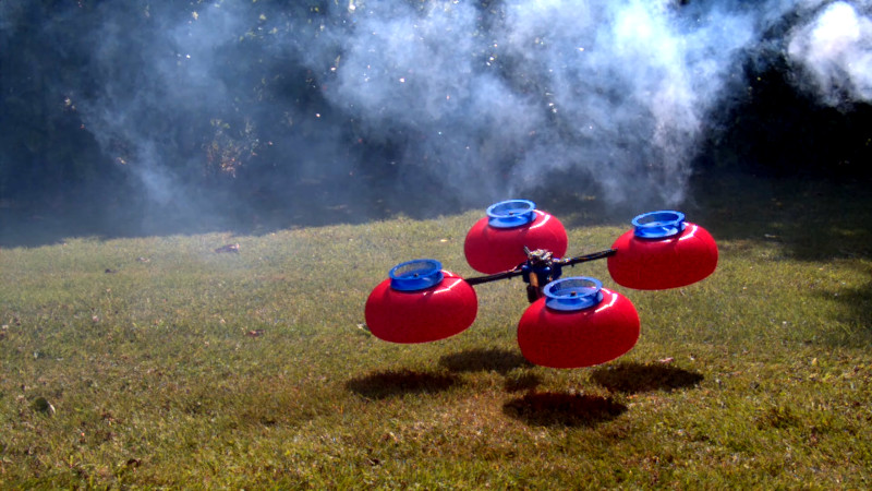
In testing, the drone was unable to fly outside of ground effect, with its weight exceeding its maximum thrust. However, [Tom] noted that the Coanda domes helped create a cushion of air when flying in this ground effect region that was far more than experienced with a typical prop drone.
Wanting some further success, [Tom] then replaced the impellers with standard drone props. This greatly improved performance, with the drone now able to fly out of ground effect and use far less power. However, its performance was still worse than a standard drone without Coanda domes fitted. [Tom] suspects that this is due to the weight penalty most of all.
While it’s unlikely you’ll see Coanda effect drones going mainstream anytime soon, [Tom]’s project goes to show that you can perform viable aerodynamic research at home with little more than a 3D printer and a fog machine. There’s plenty more fun you can have with the Coanda effect, too. Video after the break.
[Thanks to Käpt’n Blaubär for the tip!]


Wanted to make something like this sometime ago, but with one big impeller and vectored thrust with flaps on sides. The biggest problem here is that those domes and impellers are many times heavier than standard propellers and that uses up all the thrust.
The first idea that entered my mind is to use helium filled balloons instead of heavy 3d printed domes… Or perhaps vacuum formed sheets of plastic?
Then you’re just making a blimp with more steps
Lockheed and other manufacturers have actually been working on hybrid concepts over the past couple decades. True, it’s kinda like a blimp with extra steps, lol, but those extra steps might offer extra benefits. For instance, using the Coanda Effect on a lighter than air, or near lighter than air vehicle could possibly reduce drag and the effect that cross winds have on the craft. While on the other side of it, the lightness of the craft offers huge efficiencies in propulsion and lift.
Clever
Really awesome idea .. This is just a thought,
.you had success .
This is where I feel your efforts to continue experiments were a waste.
The motors you were using were built off design. or a class of power to weight/load .
And within that design the Kv was matched with certain props with specific pitch to be used .
So one does not underpower or burn up the motor…. Choose your best impellor and have a motor design built to your data. You may find your Coander effect a great success within a certain class of drone …. But certainly not against a good 3″ race drone .. as the Coander will really on to many variables to be as accurate and agile. Maybe in a class of longer range flight to battery weight while securing a payload with the increased efficiency of your Coander effect drone .. hope that helps.
I am curious (though not curious enough to try it myself…) if the dome could be made much less massy by forming it from 100 micrometer (or, better, 50) mylar film. Minimal structure would be needed– just at the boundaries– as the air flow over the surface would tend to hold the dome form.
Still not likely to make it more efficient than properly designed props, but might be a lot quieter.
Maybe just standard kitchen wrapper film would be enough?
Some of the cheaper drink pet bottle? the one that are really thin?
I think the author is totally underestimating the advantage of vacu-forming the domes. Would love to see this done and retried.
1) massive weight improvement
2) rounder shape, rather than putting together 8 pieces
3) smooth surface.
I really think he is not giving any credit to the surface . A rough surface will tend to turn the flow turbulent. A smooth one will keep it laminar for longer. While this may reduce bull thrust, i think he will have better control over the overall flow.
Going back to traditional props was what he was trying to avoid in the beginning. Using an impeller would make the drone even safer than a normal drone. He should try this again!
My first thought was an umbrella structure – thin plastic supports for a lightweight fabric (or as suggested elsewhere, mylar) dome. Intuitively a very fine-mesh fabric should work indentically to a solid surface here, I’m curious how far that could be pushed.
Fundamental failure is in trying to push air backwards, while building it to push air sideways.
So add a concave cone on top of the convex one? Or use a squirrel cage fan.
Oops, he did … I misunderstood your point. He’s trying to get lift though, so he needs to push it sideways.
Relative to aircraft
Smoke machine,
because, you know, smoke!
B^)
BTW, I haven’t seen any Canada jokes in this thread, eh?
Why would there be Canada jokes?
Coanda/Canada
pun material.
It’s the coander effect.
No it’s Coandă
When I’m making my quattro-formaggi I want to hoover up my pasta. That’s the colander effect.
My sister-in-law’s Italian mother-in-law, in her broken English, called the colander, a “pasta-stay-water-go”.
B^)
yeah, Italians are not afraid of appearing simple in order to communicate with simpler people :-)
If you vacuum formed the domes, you could conceivably use a colander as a form … it might be worth it just for the comedy value.
My first impression was the red coanda effect domes are inflatable beachballs.
Maybe this can reduce the weight an create a stabil form with inflatable objects.
Last week here in hackaday an article about latex ballon creating (https://hackaday.com/2019/08/12/latex-bellows-from-scratch). With lower count of shades this would go.
This is a “Brick Airplane Problem” * in that quadcopters fly by creating enormous (and inefficient) downward thrust and reaction force with propellers, while helicopters try to optimize the game by generating lift over rotating wings instead, and this sacrifices one for the other and loses rather than gains.
Quadcopters win on a small scale because of the confluence of light, energy-dense and drain-tolerant batteries and high power motors, as well as electronic rather than mechanical control of the upward force that is much simpler when produced at scale (RC helicopters are still a thing, but are as complex as real ones).
What Tom seems to have done is try and meld the two, spending downward thrust trying to generate ‘bernoulli’ lift via pressure differential over the lifting surface, but not (yet) finding the “sweet spot” to make this all work. There are a lot of improvements that could be done to the quadcopter (or n-copter if you will) platform; ducted fans to decrease blade tip loss comes immediately to mind, so we’ll see what he comes up with next. His projects are always thought provoking
_____________________________
* “The Flying Machine”, Ambrose Bierce (http://www.eastoftheweb.com/short-stories/UBooks/FlyiMach.shtml)
Props and heli rotors are basically one in the same. The difference is, for a fixed amount of power from your motors, you’re expending it through a smaller disk area. Force is mass x acceleration. Double the force by doubling either of the two terms. The difference lies in which term you choose to double. If you double the mass, you double the energy required. However, if you double the acceleration, it required 4X the energy. This is why it is said that it is more efficient to move a large mass by a small amount than to move a small mass by a large amount.
Multicopter props and helicopter props do operate slightly differently. The multicopter props basically beat the air down mostly by mechanical deflection (high angle of attack, high drag), while the helicopter blades use bernoulli lift (low angle of attack, low drag).
The former is much less efficient than the latter, and operates on the point that you can make a barn door fly if you just put enough power into it. It’s just necessary because otherwise the small props wouldn’t move enough air mass for enough reaction force.
To the best of my knowledge, the moving air is the side effect, not the cause. The moving blades cause aerodynamic forces to manifest on the body of the prop/rotor blades. These forces are then transmitted through the prop hub, shaft, engine bearings and finally to the airframe. How could the airframe possibly know what happens to the air when it’s not in physical contact with it (the prop/rotor)?
The reason why it is called the Coanda effect is due to a yet unnamed effect, where a weird but mostly useless phenomenon that defies intuitive explaination by people who aren’t well versed in a topic is picked up by weird people (cranks and loonies) who use it for publicity that eclipses the original discoverer of the effect. The Coanda effect was described by Thomas Young some hundred years earlier.
Henri Coanda’s airplane didn’t fly either, but he later claimed to have invented the jet engine, and falsified his own patent drawings to “prove” so. Then later cranks further exaggerated Coanda’s claims about high lift and high efficiency to sell their own frauds.
In the end, the only useful product that came out of Coanda’s re-discovery of Young’s discovery was the Dyson bladeless fan, which isn’t actually any better than a regular fan – it just looks weird and people don’t know how it works.
Coanda effect is pretty much just a high level observation of the tendency of a moving fluid surrounded by another fluid to follow a nearby surface. We know from Bernoulli that a moving fluid along a surface will lower the pressure at the surface. The curvature that is considered desirable in the Coanda effect merely delays the reduction in fluid velocity at the surface by making it more difficult for the fluid to shear/impinge on the surface. In the case where you’re attempting to generate thrust, the curvature is only useful when there is some surface perpendicular to the desired direction of thrust. Remove as much vertical component as you can to reduce dead weight, unless you want to try to utilize that portion for some kind of thrust vectoring.
As for practicality, a typical fan produces a relatively low velocity sheet of fluid, in other words, low energy. To the best of my understanding, the benefit is the greatest when you’re working with a high velocity fluid, as it has the effect of “gearing down” the energy in the fluid. Not dissimilar to an airfoil, for the doubling of airspeed across a wing, the total force goes up by 4. Just like doubling the velocity of an object requires 4 times the energy. I’ve experimented with the subject a bit, but to really get anywhere takes either a crapton of luck (for “Looks About Right” engineering), or a lot of experimentation both physically and computationally.
If you really want to take it to the next, and most promising level, you’ll be playing with “crypto-steady” flows. Basically your flows will be periodic rather than steady/continuous at any given point. This transitions the underlying physics from high entropy shear mixing at the high-low velocity fluid interface, to something more akin to Newtonian billiard balls which can lead to greater efficiency by having more control over the desirable mode of energy transfer. This isn’t just applicable to shapes commonly associated with Coanda surfaces.
Think about it this way:
A force is generated via fluid dynamics on an object by dissimilar pressure distributions on that object. If you had a flat plate with the intention of generating a force perpendicular to it’s largest surfaces, you would want one side to be exposed to a greater pressure than the other. So you can somehow increase the pressure on one side, or decrease the pressure on the other, or both. The Bernoulli effect basically knocks away fluid that is trying to exert pressure perpendicular to the surface. There is a variety of ways to achieve this, with some being simpler than others, and some being more efficient in terms of energy utilization. Then of course, design requirements dictate what you can and can’t do.
… weight penalty and the relative vacuum created under the domes when above ground effect.
NOTAR (no tail rotor) helicopters use the coanda effect by pumping high volume, low pressure air out a slit down the length of the tail boom, forcing the air around the outer curve of the boom to create the force needed to counteract the torque of the main rotor. The rotating vent and the end of the boom is for precise maneuvering. Maybe put a central fan pushing air out thru T shaped booms with the same type of slits?
This makes me think a bit of an aerospike rocket engine (but kind of in reverse) and I wonder if any of the principles from that could be applied here. My first thought is about how to introduce fluid flow to the surface which will cause deflection.
I’m not clear on a practical application for this over the more traditional propeller system.
I suppose they’re similar in the sense that the goal is a pressurevelocity conversion. For a nozzle, it’s a high pressure to high velocity conversion. For an aerodynamic surface it’s to convert a stream with some velocity to a change in static pressure (at the surface). Interestingly, you can use a stream with some velocity to either increase or decrease the pressure. For the latter, you change the dynamic pressure to static pressure.
And no, this particular design doesn’t have any advantages. The advantage comes from the possibility of using high speed motors with similar output power (generally tend to be smaller) and use a high speed gas generator like a centrifugal impeller.
OK, so this is project is just for fun. That would be a good reason not to put too much effort into optimizing the surfaces themselves (and working on better directing impeller flow)
So you take a motor with a downward facing propeller and guess at some impeller configuration and do no calculations comparing air flow? Then you want to take said impeller and try to change it’s thrust vector from horizontal to vertical by inducing a frictional surface? Just not even close efficiencies.
I couldn’t watch the whole thing and got really bored after I learned he was not using the effect for some form of thrust vectoring of vertical thrust systems.
His CAD modeling showed the centrifugal impellers recessed into the tops of the domes so that the air would pass from the edge of the impeller ring directly onto the dome surface. What he actually printed was not at all like that. The impellers were several mm above the flat tops of the domes.
Another issue was curling the bottom edges of the domes inward. If you want the air to blow straight down for maximum thrust you don’t curl the bottom edge inward to create a turbulent flow separation, of the reduced attached flow from having the impellers too high.