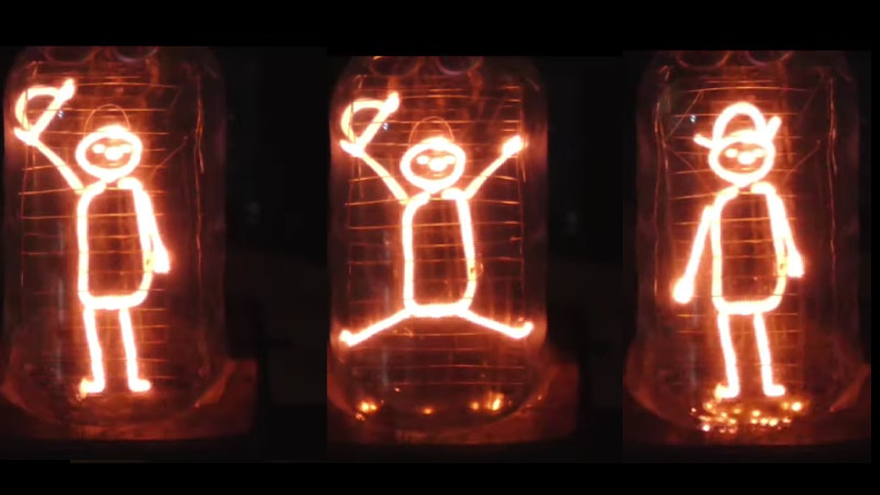
If there were four words you never expected to hear in sequence, they would probably be “Dancing cowboy Nixie tube”. But that’s just what [Glasslinger] has made, and it’s exactly what it sounds like – an encapsulated cowboy that dances.
We’ve placed the resulting video below the break, and in it we see a compelling tour through the construction of a Nixie, and the specialist tools required. Little touches such as the need to insulate with glass capillary tube whose wires which shouldn’t glow, the construction of the envelope and stem, and the painstaking layout of the various cowboy components on a sheet of mica are carefully explained.
The tube takes shape in front of us, a driver PCB is etched, and the whole arrangement is placed in a custom wooden box. This is old-school construction at its finest, with the only touch of modernity coming from an Arduino Uno that schedules the various segments. It’s not beyond imagination though to see in time gone by that a Honeywell mechanical sequencer might have been used for the same task.
We’ve brought you [Glasslinger]’s work before of course, but we’ve also seen some more conventional self-made Nixies.
Thanks [Lars Haeh] for the tip.


What a beautiful, wondersome, aweaspiring waste of time. I love it!
Ron is definitely a master artist/craftsperson worth a sub on youtube.
@ 41 minutes, tells us that the tube has failed due to arcing between electrodes at the bottom of the tube, and shows it failing, and tells us that he has terminated the project. Then he goes immediately on to mounting it in a box, and demonstrates it working. Well, I’m glad he got it to work, but it would be nice to see how.
I wondered the same. Down in the video comments he says it works for about 10 seconds at a time, and that was good enough for someone who wanted it. Not the worst kind of failure ;)
https://media2.giphy.com/media/L0snCScL0LMBor5sE0/giphy.gif
Yeeha, Yahoo, Yippie!
That’s is awesome!
Is it possible to make Nixies or VFDs using PCB Tracks as electrodes?
The main challenge is outgassing. If you make a PCB using conventional materials, like fiberglass/epoxy, these materials will, over a long period of time, release gasses into the environment, spoiling the vacuum. Even metals absorb gasses on their surfaces that have to be “baked out” before the tube can be sealed. And then there’s the adhesive that bonds the metal layer to the insulating substrate – this too will outgas over some period of time.
So if you want to use PCB methods, first you have to start with an insulating substrate that won’t outgas, such as glass or ceramics. Then you need a way of bonding metal to that substrate, that doesn’t outgas. And then you need to have a method for either applying that metal in the desired pattern (additive process) or applying it in a uniform layer and then selectively etch it (subtractive process).
I think that semiconductor fabrication processes are more likely to be a good fit, than are printed circuit fabrication methods.
You do not have to got that far. Hybrid circuit design (thick film circuits) could be a way to go: screen printed traces from glass-metal conductor (or resistor) paste on alumina substrate could be suitable for vacuum use. You can also print dielectric (insulating) pastes made from glass-ceramic compositions on traces which should not glow. Perhaps theses pastes could also be used on thin glass or mica substrates, I am not sure about there required sinter temperatures
Very good. Don’t know why I didn’t think of thick film tech.