After initially working to create a modernized replica of a Czechoslovakian 4-digit Metra M1T242 voltmeter, [Jaromir Sukuba] figured that while he was at it, he might as well create a voltmeter that would be slightly more capable. This led to the design and construction of a brand-new, 6.5 digit voltmeter design, which [Jaromir] has documented over at EEVBlog.
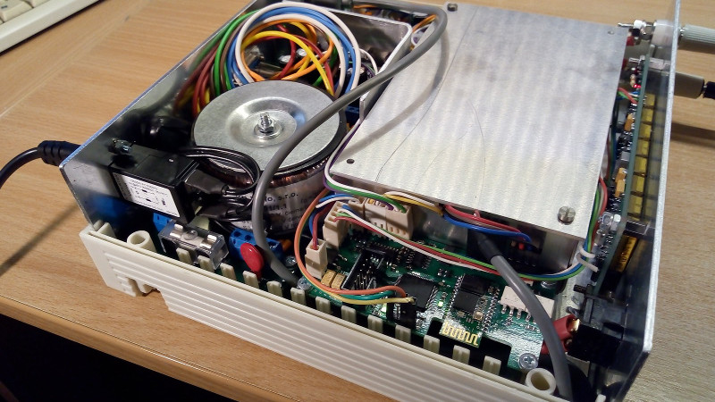
Employing an MSP430FR5994 MCU for the digital board, and an Altera/Intel EPM240T100 CPLD plus ADC on the input side, the design has been undergoing validation for a while now. The current revision uses an OPA140 op-amp in an integrating ADC setup in a multi-slope run-up configuration, but [Jaromir] has plans to replace this input board with another op-amp in a more efficient topology in the future.
Validating a voltmeter is the real challenge here, with determining the ADC noise and overall stability of the measurements. Here the ability to validate one’s design is of course limited by the quality of the testing equipment one has available. As there’s no ‘perfect’ level, it means that there will always be room for further improvement, which is both a blessing and curse with a DIY meter like this.
[Jaromir] has made the schematics and sources (firmware and Verilog HDL) available via the EEVBlog page, allowing anyone to start on their own version, or even contribute to the project. That is, assuming that one look at the internals of the prototype system hasn’t already filled you with too much respect for the sheer complexity of such a project.
(Thanks to David Gustafik for sending this one in)


This seems like a horribly slippery slope to madness…
Not that I should really comment as I sit here trying to figure out how to refine my plans to build an absurdly stable clock.
Holy heck. He made himself a 24-bit dual-slope converter. And using an LM339 ref. This dude is too cool.
But good luck refining that front-end. Accuracy + resolution is yet another rabbit-hole to fall into…
Hmm indeed And about the reference, though going to the trouble for so many ADC bits you’d surely want to consider key issue of thermal stability ie crystal type calibrated oven or far better these days a (low noise filtered) polarity switched Peltier for minimal power consumption handling both cold and hot conditions eg 20 above and below ambient or even more ideally with some alert if outside best error margins…
Nice project, provokes a few other ideas ;-)
Thanks for posting, Cheers
LM399 has its own temperature chamber – this is the component that is main contributor to long term stability (apart from LT5400 resistor networks). Stability of oscillator is not that critical, low jitter is good to achieve low noise in AD results. Standard cans with crystal oscillator are perfectly OK.
Thanks. The resolution is actually better than 6,5 digits (displaying 7,5 digits, but the last digit will be blanked later) and I checked linearity (first thing to have in order to achieve accuracy) to be within one or two ppm (measured against another 6,5 digit meter though, but at least it shows no major linearity problems. Better meter for finer results is on way). I already made better front-end with bootstrapped LTC1052 and it looks to work very well.
Of course in the late sixties there were projects about building DVMs, though not as many digits. Usually discrete components to convert to digital, and ttl for the logic. I think even one was modularized,to use the same counters and display for various things, like a frequency counter.
Things really took off when DVM ICs came along. Some were in two ICs, but soon only one, and Intersil’s DVM ic, two versions for LED or LCD, really made it easy, landing in endless cheaper DMMs.
And before one knew it, a 3.5 digit DVM is practically a gift some stores likes to toss in for free.
It is easy to count a lot of digits, but with each new digit, lower and lower order issues creep in. A 3.5 digit volt meter that reads 200mv full scale reads down to the mv. You can read a real thermocouple with one of them, but not well, you get a imv change for 18 degree c. As you add more digits things get more sensitive, and remember that every dissimilar junction is a thermocouple. Noise starts to get to be a bigger issue, any little offsets in any input stages or the comparitor, even the input voltage and temperature of your reference need to be controlled. I am not saying it can not be done, but you are getting into where you have to be very careful regarding accuracy and precision. As the person working on the clock above states, it is easy to have a lot of digits, getting them to be correct is the snag. BTW in your case I would go for a surplus rubidium standard from eBay. I always wanted one of them myself. I have a very cool old Chronolog clock that use the “hex” dot type LED displays and is just a cool old piece. By default it used the AC line frequency, but it has a TTL level input….
Your comment struck me as unnecessarily inflammatory and ill-informed. The EEVblog forum appears to be the original place the details were published, and I for one think there’s a ton of other fantastic content in that particular “cesspit”.