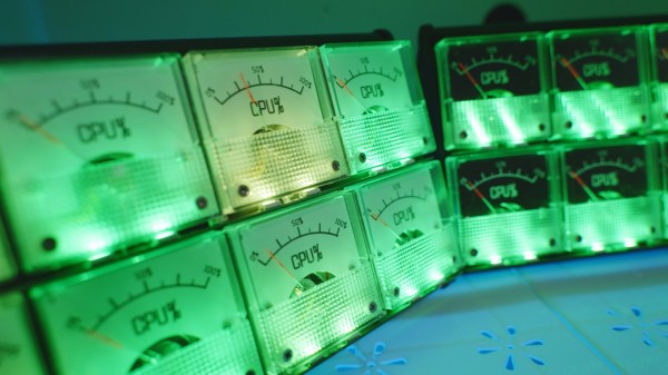
[lcamtuf] is not just a calculator superfan, but also a skilled builder. That much is evident in the fabulous design of Calcumator 2000, an electromechanical calculator that uses voltmeter readouts as digits (plus one at the bottom to represent decimal place). There are plenty of high-quality build images, so give it a look!
Calcumator 2000 is a bit of a love letter to a time when display technology hadn’t quite yet produced anything suitable for calculator use. This resulted in calculator designs that are generally unrecognizable compared to the 7-segment display based devices we see today. The Calcumator 2000, in all its electromechanical glory, would have fit right in that era.
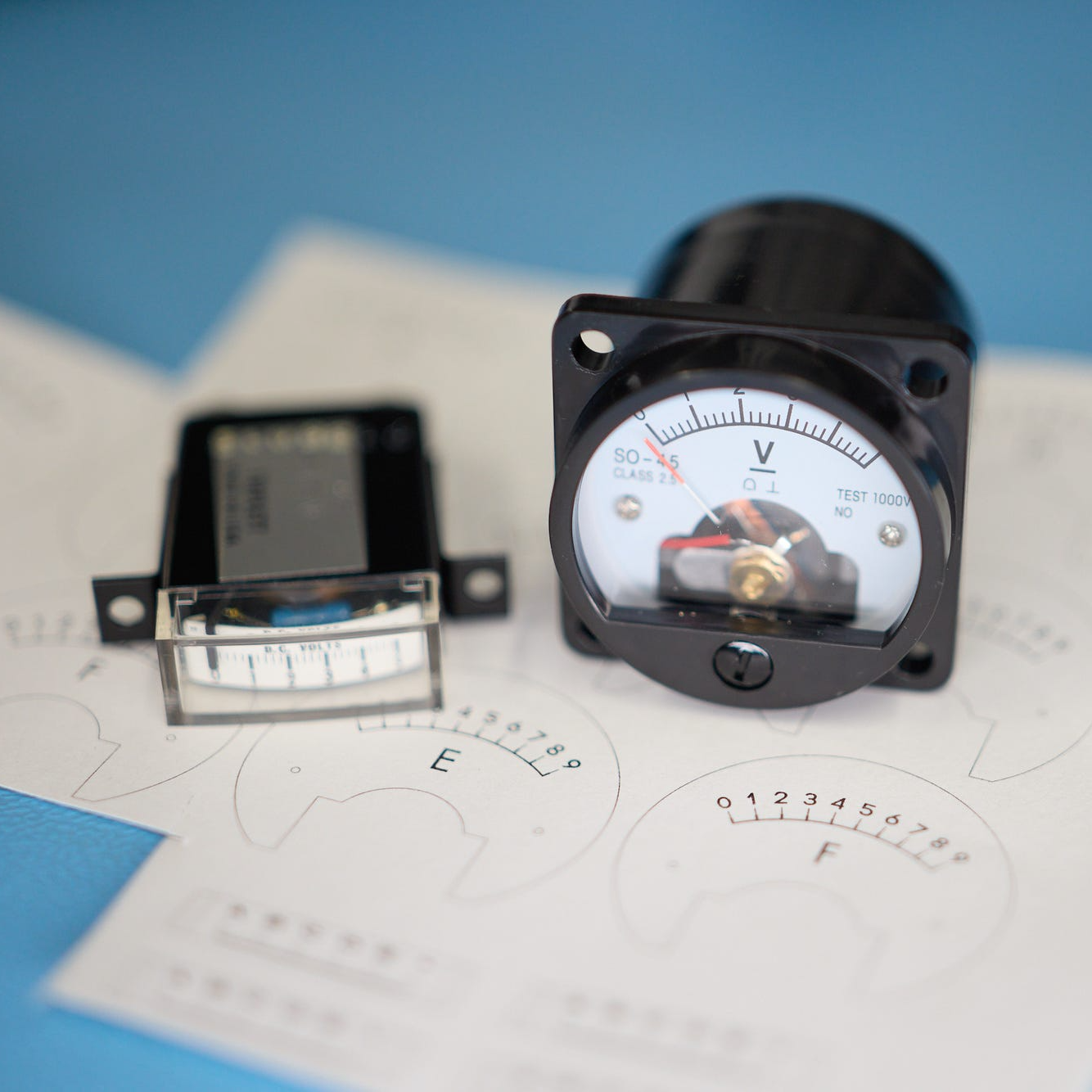
The Calcumator 2000 has all the usual buttons one would expect from a simple calculator and drives a total of seven readouts, one of which acts as the decimal point. The idea of using voltmeters as digit displays came from [lcamtuf]’s voltmeter clock, an earlier work with a similar attention to detail in its design and assembly.
We want to take a moment to admire how clean the blue panel is. [lcamtuf] made it by painting one side of an acrylic panel, cutting the letters and design out on a CNC mill, then filling with white paint. The depth of the cuts gives the white elements a nifty multi-layer effect that really complements the design.
Want to see it work? Oh yes, you do. Check out the video, embedded just below.
Continue reading “Voltmeter-Based Floating Point Calculator Does It In Style”