We’re used to extending our network connections and being no longer constrained in our use of Ethernet by proximity to a switch or hub. Our houses routinely contain wireless networks, and of course powerline-Ethernet units passing data over our mains wiring. [Peter Franck] had a similar problem but without the mains power, for a distributed sprinkler system he needed to send Ethernet over DC cables.
The solution is a surprisingly simple one, taking one of those powerline Ethernet units and converting it by removing its mains power section. These devices contain the Ethernet and powerline modem chip with its associated circuitry, and a small switch-mode power supply. He’s removed the power supply and put in a capacitive coupling to the DC cabling, resulting in a relatively inexpensive DC powerline network device.
Powerline Ethernet devices are not without their own issues, for instance they are not popular with radio amateurs due to their effect on the RF noise floor. We’d therefore be curious to see what the RF emissions are like for this hack, but we still think it’s a useful weapon in the armoury as well as something to do with all those surplus powerline Ethernet bricks.


excellent
let me buy one, fully-assembled #EoDC unit
Probably not an RFI issue, since sprinkler wiring is buried?
This is quite smart. I can imagine replacing the cable would have been tough… but considering the 30m distance…why was wifi not an option and sending only power through the cable?
Where did you get the 30m from?
To quote the source: “The purpose of this hack is powering and connecting multiple Raspberry Pi computers controlling a 24V DC solar irrigation system in a remote place with no AC or network line in reach and just 3 wires in the ground.”
Possible reasons I see:
1. W-LAN and water from an irrigation system isn’t the best combination.
2. keep the air free from unnecessary low-usage networks. different networks for irrigation system (red), yourself (green) and guests (yellow/orange).
3. better reliability
4. PXE/etherboot/netboot
To quote the source: “transmits 100 MBit/s over a thirty meters spool of telephone cable”
Second point under “some data:” on Peter Franck’s site.
Now obviously we don’t know if any/all of his runs were 30 meters but the point still stands that given those distances WiFi could have reached the devices. On the other hand there may not have been a good way to implement wifi.
Well, the location where this is going to be deployed has topological difficulties that would render a WiFi system very costly. Having said that, there is a WiFi uplink to the internet from one of the nodes.
BTW: the telephone cable was just meant to be an example lab setup. Actually, the deployment scenario is various lengths of 2.5 square mm power cables. 100 MBit/s is absolutely not necessary for the application. It just leaves a comfortable margin for signal attenuation in the field. I can add some more data when it will finally have been deployed.
Please share more once you have details. I am quite curious how this will work. I would normally think of using RS485 for this, but then it gets complicated when you actually want internet access instead of just a serial link.
It will be deployed at summertime. Stay tuned.
Yeah very good idea, hackers will have a field day.
Nice hack.
Several commercial underwater robots use this technology (albeit implemented on a custom pcb)
Ethernet over phone line! Yay!
I was sad to see Arcnet die. One hub, cheap phone line to each room, cheap coax around a ring of PCs within a room.. that was great!
Could only have been about 5 years before doing it all in 10/100 base T came down below total cost. Running 10 base 2 through the whole house was pretty decent even until media files got large.
For giggles sometime I’m gonna try making baluns for 50 ohm to 300 ohm and try connecting vintage PCs with coax cards through Cat 5 runs.
You might be able to abuse an ethernet card transformer for that :)
10Mbit Ethernet ran just fine on phone line, and I don’t mean the twisted cat3 kind. Was it noisy? Yes. Did it allow 100 meter distance? Dunno. Never tried more than ~30, but guessing 100 would have been a stretch. 100Mbit over Cat3 was fine too in a pinch.
It’s a nice idea, but for a sprinkler system does he really need 100MBit/s? I would guess some old RS232 would be enough for some command and status. IC is less than a dollar i guess, EMI is much better and it will work for hundreds of meters (depending on speed).
I just wonder if TCP over RS232 is a thing? Is there an RFC for this?
Been around a long time. Used over modems before home broadband became common. SLIP or PPP.
modems = telephone modems, btw.
RFC1055.
rs485 instead? I’ve used that on a farm years ago..
I considered RS485. However, you can run either RS485 OR power over the wires, not both.
This seems like a nice and cheap alternative to the commercial EoC [1] products. If it works over coax the RF emissions probably wouldn’t be of (such) concern.
Note to self: Test this with your old 11mbit HomePlug adapters.
[1] https://en.wikipedia.org/wiki/Ethernet_over_coax
If you’ve got coax, screw Ethernet over DC, just use WiFi and a pair of bias-tees to inject/remove the power.
I’ve seen this done before on HaD (maybe without the power injection) but what about the throughput? AFAIU WLAN and powerlan are both half-duplex but WLAN uses either 2,4 or 5GHz while HomeplugAV is between 2 and 68 MHz(!).
The later seems far better suited for normal coax cabling (the ones used for DVB-T/S2).
correction: 2-86 MHz (and the AV2 ones use MIMO, though still half-duplex I think.)
You just need decent enough cable, and it doesn’t even need to be THAT good. Losses over coax are linear with distance, they’re quadratic for free space propagation. Cabling always wins.
Over 100 ft you can use pretty much anything you want RG-6 with F connectors is still only going to be like, 20-30 dB loss, which is the equivalent of free-space with 20 dBi gain antennas on both sides.
Can this hack be used to keep ethernet over powerline running in the event of a blackout ?
By just powering the ethernet over powerline adpater with battery power ?
Yes, that’s absolutely possible. Homeplug AV does not necessarily need power on the power wires. It has been proven by this hack.
You can easily “UPS” the adapters by supplying 4.5 to 17 Volts to the modem circuitry but take extreme care when hacking them to stay on AC mains to avoid safety issues.
Thank you very much for this information!
A good idea, I wonder if the powerline devices would perform any better in this case too, with the noise reduced. Heck they might perform better without a blackout just by being powered from a more stable DC source..
If you remove the switching power supply as described in the original posting it would in deed reduce the noise on your medium. However, the effect may be negligible since the original circuit provides inductors L2 and L4 as a low-pass filter between its internal power supply and the medium.
This type of tech is actually being standardized as single pair Ethernet in IEEE and will be making it’s way into cars and industrial plants. Allegedly early tests even got it to work over two spools of barbed wire!
I actually considered using these automotive chips: https://yamar.com/product/dcb1m/ but it seems to be too early for general use. They only have engineering samples in an elevated price range on offer so far.
Ok that’s just amazing and needs to be everywhere right now. I’d love to see 2.1mm plugs with this replace USB for Arduinos. If this ever makes it into an Espressif product it will be so useful!
EoP (as opposed to PoE)
I did this once (happened as a side effect really). Hot a pair of AV200 tenda units, supposedly broken. Did some digging, supplied external 3V3. In the process, i figured i should test the connection without AC power between the units. Sure enough, it worked at full 100Mbit.
Pretty nifty hack. Too bad there aren’t any consumer devices, that would use existing powerline chipsets but allow you to use any type of compatabile wiring you want.
100 Mbit???
The units in question are rated 600 – what causes them to drop to 100? Use of older pre-gigabit Raspis?
I chose the ones with a 100 MBit Ethernet interface for power consumption reasons. They were supposed to be the least power-hungry devices by spec. The modem is probably potentially faster than 100 MBit.
You could choose the ones with a GBit Ethernet interface where power consumption is not an issue.
By “ones with 100 mbit Ethernet” – do you mean the raspis, or are the modems advertising 600 megabits but without a gigabit port?
Let me quote https://www.tp-link.com/us/home-networking/powerline/tl-pa4010/
“Interface: 1*10/100Mbps Ethernet Port”
So the limiting component is the Ethernet interface of this specific HP/AV adapters. Since I don’t even need 10 Mbps in my application I happily traded power consumption for speed.
If you have a need for speed and you don’t care about an extra Watt, TL-PA7017 would be your best bet. Though I haven’t tried it out personally I would expect a very similar design except for the Ethernet interface part. At least from the outside they look very very similar.
see https://www.tp-link.com/us/home-networking/powerline/tl-pa7017-kit/ for specifications
These ones are featuring a 10/100 Ethernet port:
https://www.tp-link.com/us/home-networking/powerline/tl-pa4010-kit/
These ones are featuring a 1 Gbps Ethernet port:
https://www.tp-link.com/us/home-networking/powerline/tl-pa7017-kit/
So yes they are somewhat advertising a bandwidth that you won’t ever reach end-to-end.
If you used these on the common-mode center taps of PoE, could you do EoPoE? I’m actually curious if you could get gigabit speeds on the ethernet itself (despite the added common-mode noise) plus whatever speed you get from the powerline adapters, to increase total throughput.
I would rather try multi-GBit interfaces to increase throughput in a scenario where structured cabling is already installed. I strongly doubt PLC will increase overall bandwidth on top of GBit ETH, with or without PoE, though I haven’t actually tried it.
Your idea inspired this nefarious possibility:
Could it be possible to establish a hidden/dark net through a PoE switch to jump VLANs?
Basically connecting two compromised devices equipped with powline-LAN adapters on the common-mode center taps to two ports of a PoE switch on different VLANs.
Depending on how the switch “does” its PoE it should be possible, shouldn’t it?
Seems feasible — but if you just want to stay on PoE-land this is a tad easier : https://store.ui.com/collections/unifi-network-switching/products/usw-flex
Have you tried a longer cable runs?
Not yet. Deployment will be carried out during summer 2020. I would expect the DC version to allow for a communication distance similar to running the same devices on AC lines.
Hi everyone, I am trying to implement this hack with a pair of TP-Link AV600 powerline adapters. However, I was thinking of setting the transmission line voltage to 48V instead of 12V. Basically, I will be using 12V for powering the signaling circuit and 48V for transmission. Do I need to make the ground common? Or both the grounds should be isolated?
Any help is appreciated.
Hi Abhilash Ingale,
Your Application should be functioning just fine. The DC voltage on the transmission line doesn’t matter as long as it is lower than mains Vpp (roughly 330 VDC).
The different grounds should be isolated.
The Modem circuit is isolated from the line circuit by design.
Peter
Thanks Peter.
I have a follow-up question.
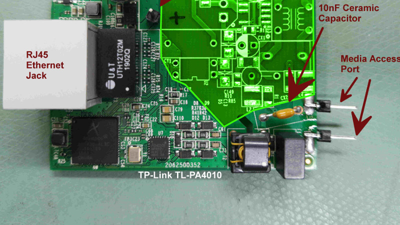
I read that these decoupling caps are for filtering high frequency noise from the input. I do not have a10nF ceramic cap.
Could I keep the existing caps if I am okay with a little noise / loss in data transfer speed? Will it be good enough to demonstrate its working?
Please help.
The capacitor is not meant for noise reduction because in this case the “high frequency noise” is the actual modem signal ;-). The series capacitor’s function is a high pass filter that couples the high frequency signal of the modem into the medium.
Long story short: the original capacitor is just fine!
I replaced it only due do its bulky form factor. You definitely don’t need to do that.
Thank you for the insight, Peter!
One more request –
I need your assistance in removing components from the AV600 PLC receiver (please refer the link for images). I am confused on which components need to be removed in the red bounding box area? Which of the capacitors should I keep and which of them should I desolder ?
I am a newbie and not experienced enough to read multi-layer PCBs. Besides, this powerline adapter is not readily available in my country and hence, I don’t want to make rookie mistakes. I hope you would be able to help me out here.
( Drive link – https://drive.google.com/open?id=1aTOFlh7yqFL8tstmnm1XYTQA_-bwurfl )
I think you need to keep C1, R5, D6 and the maroon colored brick (a fuse that was black in my device).
Check if one terminal of C1 connects directly to the ferrite transformer. If yes, that is the right component to keep.
Anyway, mark the capacitors in order to remember which one was where, so if you removed the wrong one, you can just put it back in and all will be fine. Don’t worry. You won’t break it.
Hi Peter,
Thank you so much for the time that you are putting in. However, I did not understand which transformer you were referring to when you said ferrite transformer. Is it the ‘big one’ or the ‘small one’?
Oh, I’m very sorry for that.
The component I tried to refer to is marked “T4” in your circuit.
The dark square thing with 4 terminals, a few turns of tan wire on a core, a little white dab of white paint on top and the PCB slit cut underneath.
Ok Peter, I have started working on it. I should be able to post an update (on this thread) by tommorrow.
Thanks!
Hi Peter,
So I wanted to share some developments. I desoldered the unnecessary components on both the adapters and have put the pins for powering the signaling circuit. Could you please check the polarity on the receiver? Please take a look at the image. The polarity of connections seems to be reverse of the transmitter adapter; I checked the continuity of one terminal with negative pin of electrolytic cap.
Also, how should I connect the transmission cables? Will polarity matter there? If yes, could you please point out which ones should be positive and which ones should be negative (consider the orientation in the attached photograph) ?
Soon after this is resolved, I would wiring it up and sharing thee updates!
Hi Abhilash,
I cannot reliably tell from the pictures the correct polarity of the power input.
As i remember it there should be a series diode to protect you from damaging anything by reversing the polarity. You are absolutely right that the negative power input shall be connected to the negative terminal of the large electrolytic capacitor.
The power input polarity must match the capacitor polarity.
The polarity of the line terminals is irrelevant. Either way will do. For a testing setup i would suggest you to connect the devices by just two wires on your bench. Applying voltage to the line is not necessary for them to function.
If you plan to continue hacking SMT stuff you should possibly get in reach of a hot air gun eventually ;-)
Hi Peter,
Thank you again for clearing the doubt. I have wired up the system and as you suggested, will try to test them without voltage first. Will update you soon about the outcome.
And yes, I will try to get some stuff that would ease handling SMT stuff and keep things a lot cleaner. Thanks for the suggestion!
Hi Peter,
I could successfully implement the hack as per your directions.
I also conducted a few tests on different line voltages (0V,12V,48V) and I am getting at least 50Mbps download speed (the fluctuations could be because of my breadboard connections or internet service provider as well). In practical terms, I could stream 1080p 60fps YouTube videos without buffering.
Overall, this hack works like a charm! Thank you for all the assistance with the build.
Hi Peter,
Sincere apologies. I forgot to share the photograph link. Please find it here – https://drive.google.com/open?id=1VYN8EF1m1MyIVHu_epVCgWdXlOmo_Xlx
Hi Abhilash,
you are absolutely right in that respect that the negative supply input is the one that must connect to the negative terminal of the large electrolytic capacitor. I can’t see it reliably in the picture so consult your multimeter to check.
Input polarity must match the capacitor’s polarity!
The polarity of the transmission line does *not* matter. For testing purposes i would suggest you to connect just two wires between the devices. There is no need to apply any power to the line in order to transmit data.
If you continue to hack SMT stuff you should probably try to get in reach of a hot air gun eventually ;-)
Inverting the PoE concept. The powersupply used to transport LAN. Why did you never used PoE?
Hi Peter!
Do you have any idea what the optocoupler is used for?
I did a teardown of a TL-PA7017 and the PCB looks pretty similar. However, it uses a Broadcom BCM60350 as SoC.
As the sender diode is connected to the primary side I could only think of AC zero-cross detection.
If so, what is it used for?
Hi Nanosonde,
the optocoupler is typically used as an analog feedback from the secondary to the primary side of the AC switched mode power supply. It sends an analog power regulation feedback signal controlling the duty cycle to the mains part of the SMPS.
I simply removed it because you don’t need it if you power the modem directly.
Hi Peter,
thanks for the reply.
I investigated furher and traced the optocoupler connections.
The optocouplers in the powerline adapters (TL-PA4010 and TL-PA7017) are not used by the SMPS.
The TL-PA7017 uses a OB2500N and they advertise it especially with the fact that an optocoupler is not required as it does primary-side sensing and regulation.
The optopcouplers in these powerline adapters are used as zero-crossing detection circuitry.
I found the following sentence in a PLC module from Codico:
“Zero-cross detection has to be used in all applications with communication over AC mains or when module’s
power supply is powers from AC mains. Two or more HomePlug AV/GreenPHY logical networks can only coexist
when zero-cross detection circuit is implemented”
The HomePlug AV module from Belfuse states:
“Zero Cross Detector Input. This should be provided from a safety isolated source
(opto-isolator). The waveform is to correspond to the polarity of the AC live waveform.
For dry wire or DC safety this should be connected to VCC via a pull up (10kΩ). This
information synchronizes the channel adaptation of the Powerline chipset to the line
cycle periodic noise present on the power line.”
So for this DC-Hack it seems to be ok to just not use it. However, I would assume that it should not be left floating.
BTW:
The TL-PA7017 Kit with the Broadcom chipset is also working fine with the DC mod applied.
The chipset has a heatsink and it becomes really hot without it.
Both adapters are running from a 12V supply and both together draw a current of approx. 300mA with an active Gigabit LAN connection. The tPLC utility shows a connection speed around 600Mbps in both directions.
I tested the TL-PA7017 Kit in Version 3 (V3) for the European market. There also seems to be a V4 version.
Interesting! I did not dig so deep into the circuit. A zero cross detection makes sense for AC. I ripped out the opto entirely.
It may have worked immediately because they may have designed in an internal pull-up resistor on the phase detection input of the modem chip. If it ever fails I’ll pull it up externally, so thanks for the comment!
This looks very promising. Would this work as a master slave comm configuration? I.e. connect multiple remote devices to one master device and communicate to all devices. Or is it a point to point config.
Does that mean this can also work with low voltage AC? Eg 16-24VAC used for doorbells?
Yes, it can work on low voltage AC lines as well. It could even be powered from these by adding very few components (rectifier, capacitor, regulator).
Can this PLC hack be used to piggy-back digital data on top of analog video signal line (single pair)? Would the PLC on the other end be still able to separate the digital data?